
Voltage Measurement
'Voltage Measurement' hardware is often used when the voltage is measured directly by a multimeter connected in voltmeter configuration.
When clicking on the “Voltage Measurements” picture, the following menu appears on the right side of the schematic editor:
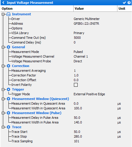
Instrument
- Driver: select the appropriate driver corresponding to the instrument (refer to Supported IV Measurement list)
- Address: set the communication address. Note the
 icon can be use to open the Instrument Scanner
 - Options: set the specific driver options clicking on
 icon (refer to Supported Instruments section)
 - VISA Library: set the VISA Library (*.dll) used to communicate with the instrument (see help on this page: Getting Started : "Configure the VISA Library on the control PC")
- Command Time Out (ms): elapsed time before returning an error message if no response from the instrument
- Command Delay (ms): delay before sending a command to the instrument
General
- Measurement Mode: choose the measurement mode (DC or Pulsed)
- Voltage Measurement Channel: select the voltage measurement channel
- Voltage Measurement Probe: various voltage measurement methods can
be used. There is a list in the drop-down menu:
- ‘Automatic detection’ has to be selected when using the AMCAD PIV system
- ‘Direct’ means that the voltage is directly measured from the instrument (used with standard DC supplies or voltmeter)
Correction
- Measurement Averaging: set the averaging.
- Correction Factor: set a correction factor, which multiplies the value of the measurement (useful when IV Pulsed measurement is impossible)
- Correction Offset: Set a correction offset, which adds (or subtracts) a constant value
- Invert Polarity: Check this box to invert the polarity. The inverse polarity is used when the positive and ground terminals of a single quadrant power supply is used to feed and measure a negative bias voltage. Even though the instrument will return a positive values, IQSTAR will automatically return the inverse of this value
Trigger (available only in Pulsed mode)
Select the Internal or External Positive/Negative Edge Trigger. Basically, the external positive edge trigger signal comes from the VNA or the RF Source.
Measurement Windows (Quiescent) (available only in Pulsed mode)
- Measurement Delay in Quiescent Area: set the delay of the quiescent measurement window
- Measurement Width in Quiescent Area: set the width of the quiescent measurement window
Note: These timings can be re-adjusted in the 'Chronograms' tab.
Measurement Windows (Pulse) (available only in Pulsed mode)
- Measurement Delay in Pulse Area: set the delay of the pulse measurement window
- Measurement Width in Pulse Area: set the width of the pulse measurement window
Note: These timings can be re-adjusted in the 'Chronograms' tab.
Trace (available only in Pulsed mode)
- Trace Start: set the trace start.
- Trace Stop: set the trace stop.
- Trace Sampling: set the trace sampling.
Note: These settings are used to record a time domain IV screenshot.
This feature is only available using an oscilloscope.