
RF power sensor matrix
In the IQSTAR schematic, the RF power sensor matrix can be use to drive, in top of regular input, reflected and output power sensors, additional power sensor anywhere in the setup. This instrument allows to add up to 10 additional power sensors that can be managed using RF Power Sensors Manager or monitored using Hardware monitoring tools.
When clicking on the "Thermal Controller" picture, the following menu appears on the right side of the schematic editor. Using the "count" setting, the number of additional power sensors can be adjusted.
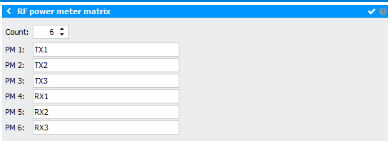
In this menu, it is possible to give a name to each additional power sensor.
Also, the main window is updated :
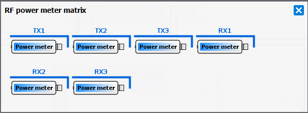
Power Meter

When clicking on the “Power Meter” picture, the following menu appears on the right side of the schematic editor:

- Driver: select the appropriate driver corresponding to the instrument (refer to Supported Power Meters list)
- Address: set the communication address. Note the
 icon can be use to
open the Instrument Scanner
icon can be use to
open the Instrument Scanner - Options: set specific driver options by clicking on
 icon (refer
to Supported Instruments section)
icon (refer
to Supported Instruments section) - VISA Library: set the VISA Library (*.dll) used to communicate with the instrument (see help on this page: Getting Started : "Configure the VISA Library on the control PC")
- Command Time Out (ms): elapsed time before returning an error message if no response from the instrument
- Command Delay (ms): delay before sending a command to the instrument
- Mode: choose the measurement mode (CW or Pulsed)
- Channel: select the channel (for a single-channel power meter select 'Channel 1')
- Power limit: set the power limit of the power sensor to prevent any damage. IQSTAR will stop automatically the measurement or calibration process if the power value read by the power meter is higher than this value
- Averaging: set the averaging.
- Fixed Offset: set an offset if an attenuator/adaptor is added to the power sensor. This setting can also be used to calculate a peak power using an average power sensor.
- Use File: select to use a *.S2P file as an attenuator offset
- File Offset: select the *.S2P file corresponding to the
attenuator/adaptor added to the power sensor clicking on the
 icon or selecting a
file included in the Files manager of IQSTAR through the
icon or selecting a
file included in the Files manager of IQSTAR through the
 icon
Note: *.S2P file can be plotted using
icon
Note: *.S2P file can be plotted using icon.
icon. - Swap File: select to swap [S11] and [S22] in the *.S2P file
- Interpolate File: select to interpolate values during measurement/calibration
- Delay: set the measurement window delay.
- Width: set the measurement window width.
Select the Internal or External Positive/Negative Edge Trigger. Typically, the power meter is externally triggered and the same window as the RF source is used for the measurement.