
DUT Biasing
Standard DUT biasing
The DUT biasing is a separate module only accessible when the bench is initialized.
This panel is always accessible from shortcut on the right side  or expand
"Measurement" > "Hardware Control" on the left under
“Plug-ins”.
or expand
"Measurement" > "Hardware Control" on the left under
“Plug-ins”.
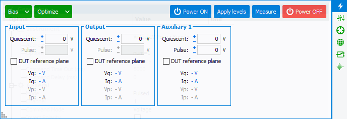
In the above case, only the Auxiliary (right) power supply is pulsed. The other are set in CW mode.
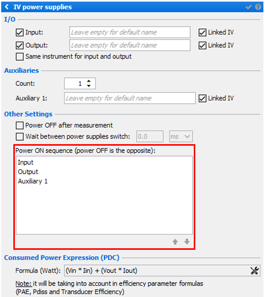
The power supplies set in the schematic will be displayed in the DUT biasing tool. Each power supply will be identified by the name set by the user during the power supplies configuration. The same parameters are available for each supply.
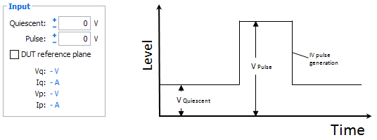
- Quiescent: set the quiescent voltage level
- Pulse: set the pulse voltage level (available only if the Power Supplies is configured in pulse mode instead of DC mode)
- DUT Reference plane: check this box to allow IQSTAR to
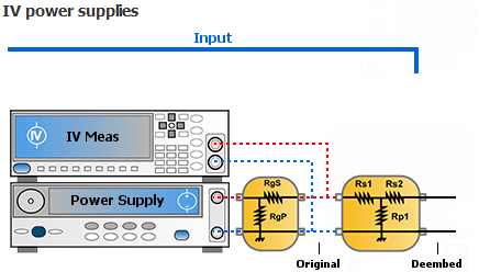
optimize the voltage at the DUT reference plane (only if the Resistive Network of the biasing is set in the schematic)
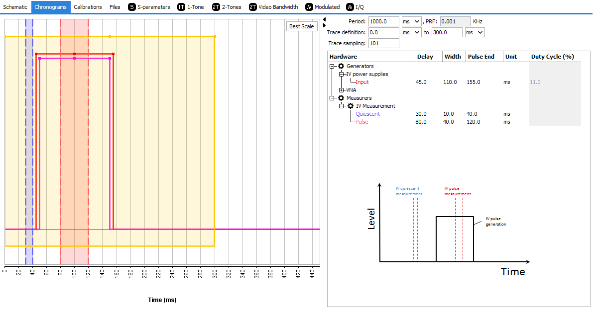
The measurement of the IV parameters is set in the Chronograms if the setup is in pulse mode.

Once 'ON', it is possible to enter the values in the bias editor, the level is only applied when 'Apply levels' is clicked. At this moment, IQSTAR applies the commands and runs a IV measurement.
Measurement can be refreshed using 'Measure'.

The bias button can expand itself with three main options:
- The create icon
 must be used to create biasing
profiles. It will trigger the save of the current biasing values entered in
the power supplies. Once clicked, a name is needed in order to be saved. On
the next click to expland the Bias buttons, this new profile will
appear under create, allowing the selection of the biasing to be applied
when clicking the Apply Levels button. When doing several profiles,
it can be used as a routine to bias a device:
must be used to create biasing
profiles. It will trigger the save of the current biasing values entered in
the power supplies. Once clicked, a name is needed in order to be saved. On
the next click to expland the Bias buttons, this new profile will
appear under create, allowing the selection of the biasing to be applied
when clicking the Apply Levels button. When doing several profiles,
it can be used as a routine to bias a device: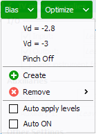
If bias is clicked, the top profile will be selected. Otherwise, directly click on a profile to set the profile values.
Once a profile is created and needs to be removed, use
 and select the profile to delete.
 - The bottom options must be used carefully. It allows the automatic submit of the level when selecting a profile, and automatically powers ON the device.
The Optimize buttonis used to select an optimization profile to apply to the current biasing. It is only available when profiles have been saved. See the next section about Optimization for more details.
Optimized DUT biasing
The optimized DUT biasing is a tool accessible when the bench is initialized. This
panel is always accessible from shortcut on the right side  . This tool
will automatically set the right biasing conditions regarding the orders and the
parameters.
. This tool
will automatically set the right biasing conditions regarding the orders and the
parameters.
When a all the parameters are filled, it is possible to either run the optimizer or to save the profile and run this optimization in the DUT biasing section.
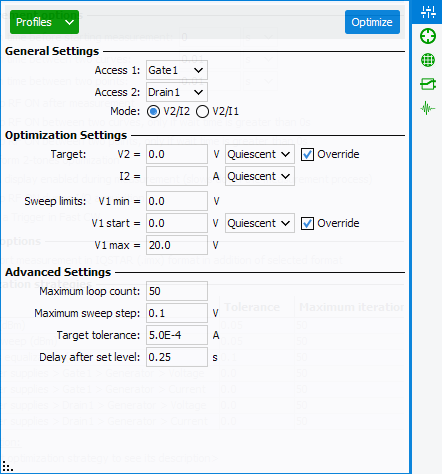
General settings:
- Set which power supply is used as Access 1 and Access 2
- Mode determines which value will be optimized, as an example V2/I2 for FET transistor will set the desired output voltage and current using V1 optimization
Optimization settings: (With mode V2/I2 selected)
- Target: set the value to reach for V2 (set by the power supply and optimized if DUT ref plane is used) and I2 (optimized using IVCAD algorithm on V1 value)
- Sweep limits: to prevent any damage, the optimizer will adjust V1 value in a voltage range defined by user
- Levels: set the level you need to optimize, quiescent level or pulse level (only if instruments are configured in pulsed mode in the setup)
- Override: When checked, the optimization setting will allow the user to change manually, if desired, the values of V1 and/or V2. If unchecked, the fileds V1 and V2 will be grayed out and the values will be taken directly from the Standard DUT biasing
Advanced settings:
- Maximum loop count: set maximum iteration for the optimizer
- Maximum sweep step: restrict the max step value used for V1 optimization
- Target tolerance: tolerance to estimate the optimization is OK
- Delay after set level: waiting time between two iterations
Once configured, click on "Optimize" button. The optimization starts and intermediate V2/I2 values appear at the bottom of the window. Once targets are reached, values V1 and V2 are set in the DUT biasing and IV measurements are updated.