
Resistive Network
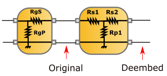
The resistive networks is used to de-embed IV measurements to the appropriated reference plane. The measurement reference plane is located at the resistive network output. The DC supply associated with the resistive network acts as an equivalent Thevenin/Norton generator with its modified equivalent internal impedance. The serial and/or parallel resistances embedded in such networks must be defined in terms of RgS of RgP in the resistive network interface. By default, the serial resistances are set to 0 Ohms and the parallel resistances are set to 1.0E8 Ohms. The parasitic resistances corresponding to the bias tees and/or the cables can be taken into account if the values are known. To de-embedd the measurements to the device reference plane, the values Rs1, Rp1 and Rs2 have to be defined.
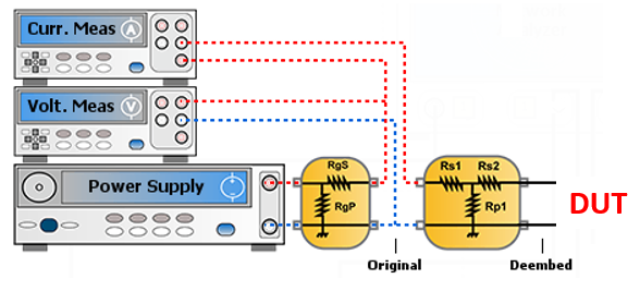
If the measurements are made using an oscilloscope, the voltages and current probes are connected to the “original measurement reference plane” . For current measurement, the differential voltage probe will be connected across the RgS resistances, while voltage and hall current probes are connected between the RgS and Rs1 resistances.
When clicking on the “Resistive Network” picture, the following menu appears on the right side of the schematic editor:
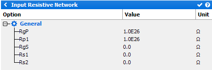
General
- RgP: set the "Parallel Generator resistance"
- Rp1: set the "Bias Tee parallel resistance"
- RgS: set the "Serie Generator resistance" (used for current measurement using the differential voltage probe)
- Rs1: set the "DC cable resistance"
- Rs2: set the "Bias Tee serial resistance"