IV Measurement
'IV Measurement' hardware is often used when the voltage and current are measured directly by the power supply. In this case, select the same driver and the same channel used in the power supply hardware.

When clicking on the “IV
Measurement” picture,
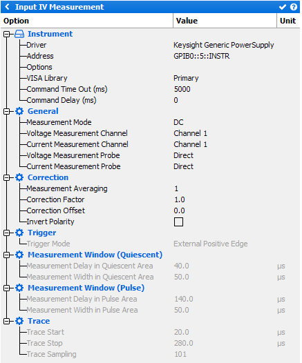
the following menu appears on the right side of the schematic
editor:


Instrument
- Driver: select the appropriate driver corresponding to the instrument (refer to Supported IV Measurement list)
- Address: set the communication address. Note the
 icon can be use to open the Instrument Scanner
 - Options: select the specific driver options clicking on
 icon (refer
to Supported Instruments section)
 - VISA Library: set the VISA Library (*.dll) used to communicate with the instrument (see help on this page: Getting Started : "Configure the VISA Library on the control PC")
- Command Time Out (ms): elapsed time before returning an error message if no response from the instrument
- Command Delay (ms): delay before sending a command to the instrument
General
- Measurement Mode: choose the measurement mode (DC or Pulsed)
- Voltage Measurement Channel: select the voltage measurement channel.
- Current Measurement Channel: select the current measurement channel.
- Voltage Measurement Probe: various voltage measurements
methods can be used. They are listed in the drop-down menu:
- ‘Automatic detection’ has to be selected when using the AMCAD PIV system
- ‘Direct’ means that the current is directly measured from the instrument (used with standard DC supplies or voltmeters)
- Current Measurement Probe : Various current measurements
methods can be used. There is a list in the drop-down menu:
- ‘Automatic detection’ has to be selected when using the AMCAD PIV system
- ‘Direct’ means that the current is directly measured from the instrument (used with standard DC supplies or voltmeter)
- ‘Differential’ uses a differential voltage probe connected across a serial resistance (RgS in the Resistive Network) to determine the current. Different measurement ranges (Automatic, Low, Medium, High) can be selected in function of the instrument its driver specifications
- 'Hall’ means that a Hall current probe is used. Different measurement ranges (Automatic, Low, Medium, High) can be select in function of the probe and the driver specifications
Correction
- Measurement Averaging: set the averaging.
- Correction Factor: set a correction factor, which multiplies the value of the measurement (useful when IV Pulsed measurement is impossible)
- Correction Offset: set a correction offset, which adds (or subtracts) a constant value
- Invert Polarity: check this box to invert the polarity. The inverse polarity is used when the positive and ground terminals of a single quadrant power supply is used to feed and measure a negative bias voltage. Even though the instrument will return a positive values, IQSTAR will automatically return the inverse of this value
Trigger (available only in Pulsed mode)
Select the Internal or External Positive/Negative Edge Trigger. Basically, the external positive edge trigger signal comes from the VNA or the RF Source.
Measurement Window (Quiescent) (available only in Pulsed mode)
- Measurement Delay in Quiescent Area: set the delay of the quiescent measurement window
- Measurement Width in Quiescent Area: set the width of the quiescent measurement window
Note: These timings can be re-adjusted in the 'Chronograms' tab.
Measurement Window (Pulse) (available only in Pulsed mode)
- Measurement Delay in Pulse Area: set the delay of the pulse measurement window
- Measurement Width in Pulse Area: set the width of the pulse measurement window
Note: These timings can be re-adjusted in the 'Chronograms' tab.
Trace (available only in Pulsed mode)
- Trace Start: set the trace start.
- Trace Stop: set the trace stop.
- Trace Sampling: set the trace sampling.
Note: These settings are used to record a time domain IV
screenshot. This feature is only available using an oscilloscope or
AMCAD PIV.
