Trigger Source
The trigger source will generate the time reference that will drive and synchronize the RF modulators which can be located in an external test set if not integrated in the VNA.

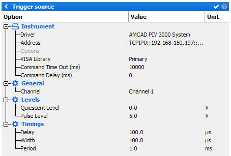
When clicking on the “Trigger source” picture, the following menu appears on the right side of the schematic editor:

Instrument
- Driver: set the appropriate driver corresponding to the instrument (refer to Supported Trigger Sources list)
- Address: set the communication address. Note the
 icon can be use to open the Instrument Scanner
 - Options: set the specific driver options clicking on
 icon (refer to Supported Instruments section)
 - VISA Library: set the VISA Library (*.dll) used to communicate with the instrument (see help on this page: Getting Started : "Configure the VISA Library on the control PC")
- Command Time Out (ms): elapsed time before returning an error message if no response from the instrument
- Command Delay (ms): delay before sending a command to the instrument
General
- Channel: select the channel
Levels
- Quiescent Level: set the quiescent level
- Pulse Level: set the pulse level
Timings
- Delay: set the pulse delay
- Width: set the pulse width
- Period: set the pulse period
Note: These timings doesn't appear in the Chronograms tab, because
it represent the Chronograms initial time (t0)
