
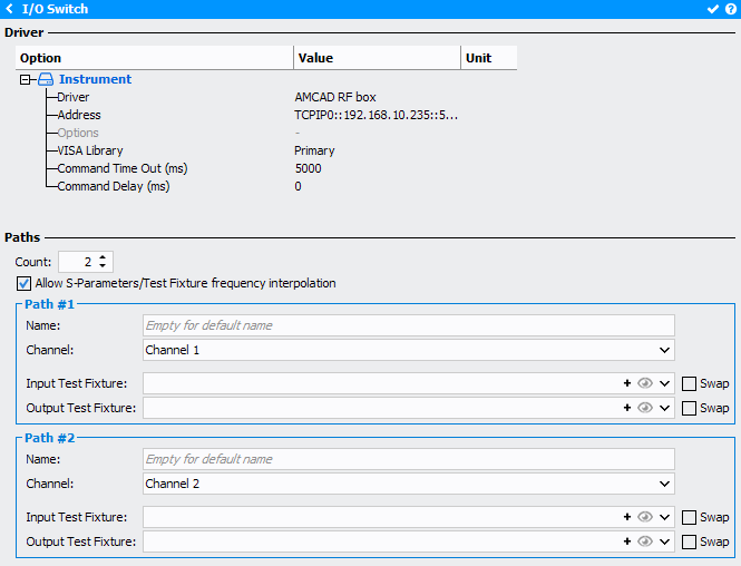
I/O Switch
The I/O Switch will allow ton controll multiple paths. To manage the switch, refer to
Switch Manager tool.
When clicking on the Input or Output Switch, the following menu appears on the right side
of the schematic editor:
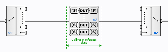
Note: Using I/O switch, the input and output
fixture can be defined on each RF path thanks to I/O switch configuration panel.
Therefore, Input & Output Fixtures defined for single path
configuration (when I/O swicth is disable in Schematic) are not
take into account.
Driver
- Driver: select the appropriate driver corresponding to the instrument (refer to Supported I/O Switchs list)
- Address: set the communication address. Note the
 icon can be use to
open the Instrument Scanner
icon can be use to
open the Instrument Scanner - Options: set the specific driver options clicking on
 icon
(refer to Supported Instruments section)
icon
(refer to Supported Instruments section) - VISA Library: set the VISA Library (*.dll) used to communicate with the instrument (see help on this page: Getting Started : "Configure the VISA Library on the control PC")
- Command Time Out (ms): elapsed time before returning an error message if no response from the instrument
- Command Delay (ms): delay before sending a command to the instrument
Paths
This tab is used to define the number of paths available (Max 10).
- Allow S-Parameters/Test Fixture frequency interpolation:select to enable interpolation on the *.S2P file
For each path, the following parameters are editable :
- Name: give a name to identify each channel
- Channel: select the channel associated in the switch
- Input / Output Test Fixture: input and output fixturesNote: Click on the
 icon or
select a file included in the Files manager of IQSTAR
through the
icon or
select a file included in the Files manager of IQSTAR
through the  icon. *.S2P file can be plotted using the
  icon.
icon.