
Power Supplies & IV Measurements
The ‘Power Supplies’ setup window includes the ‘I-V Measurement units’ as well.
When clicking on the “IV Power Supplies” picture, the following sub-schematic appears in the schematic editor:
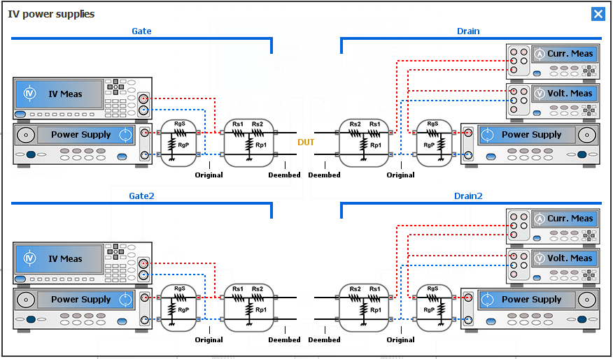
It is divided into five configuration settings:
- Power Supplies used to define the instrument supplying the DUT
- Resistive Network used to define the resistive networks (e.g. current measurement through a shunt in differential mode)
- IV Measurements Settings used to define the instruments for voltage and current measurement (e.g. voltage and current measurement with a power supply)
- Voltage Measurement used to define the instruments for voltage measurement. (e.g. voltage measurement with a multimeter, oscilloscope, power supply)
- Current Measurements used to define the instruments for current measurement (e.g. current measurement with a multimeter, oscilloscope, power supply)
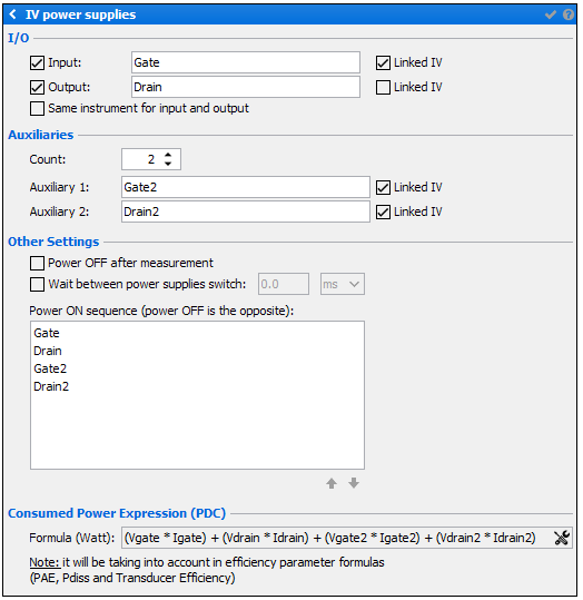
When clicking on the “IV Power Supplies” picture, the following menu appears on the right side of the schematic editor. This menu is related to the IV measurement configuration, the power supplies ON/OFF sequence options and the Consumed Power formula definition.
Note: It's possible to rename each 'IV power supplies' with a custom name (e.g. Gate1 and
Drain1), in order to make the DUT Biasing wizard easier to
use.
Auxiliaries
- Count: allows to add more than 2 power supplies access.
Note: Up to 30 auxiliaries power supplies can be added. Each auxiliary can be renamed.
Other Settings
- Power Off after measurement: checking this box will automatically turn off the power supplies after each measurement sequence.
- Wait between power supplies switch: when checking this box, the user can specify a delay between the commands sent to the power supplies during the switch ON and OFF sequence (delay between gate and drain biasing for example)
- Power ON/OFF sequence: choose the sequence for switching on the
power supplies using the
 (the sequence for switching off the power supplies
is the opposite).
(the sequence for switching off the power supplies
is the opposite). 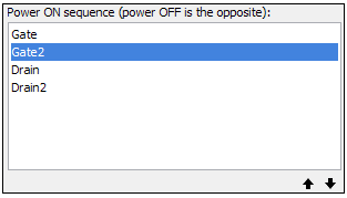
Taking into account the example above:ON sequence- Input power supply (named "Gate")
- Auxiliary1 power supply (named "Gate2")
- Output power supply (named "Drain")
- Auxiliary2 power supply (named "Drain2")
OFF sequence- Auxiliary2 power supply (named "Drain2")
- Output power supply (named "Drain")
- Auxiliary1 power supply (named "Gate2")
- Input power supply (named "Gate")
Consumed Power Expression
Select the  icon to edit and define a custom formula to
calculate the consumed power in Watts.
icon to edit and define a custom formula to
calculate the consumed power in Watts.
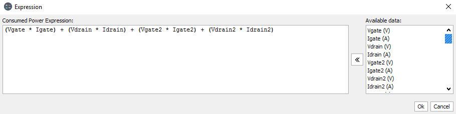
The default formula is "(Vin*Iin+Vout*Iout)".
icon to edit and define a custom formula to
calculate the consumed power in Watts.
The default formula is "(Vin*Iin+Vout*Iout)".
Note: PDC's formula defined here, will be taken in account in the efficiency parameters formula (PAE, Pdiss, Transducer Efficiency)