
Power Supplies
A total of twenty DC or Pulsed Power Supplies can be configured to provide bias signals. The input and the output supplies are the main supplies. The auxiliary power supplies can be used to bias multiple stage circuits or additional circuits if needed.
When clicking on the “Power Supply” pictures, the following menu appears on the right side of the schematic editor:
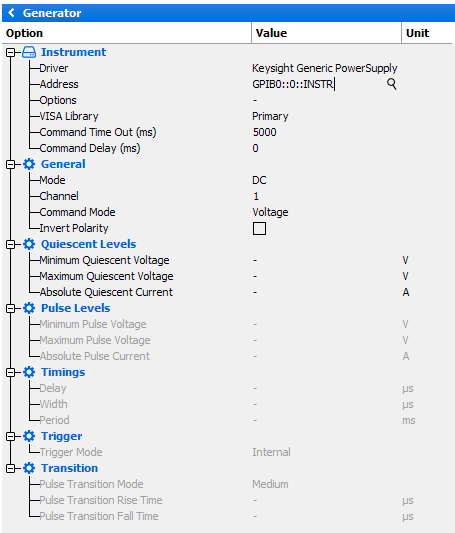
Instrument
- Driver: select the appropriate driver corresponding to the instrument (refer to Supported Power Supplies list)
- Address: set the communication address. Note the
 icon can be use to open the Instrument Scanner
 - Options: set the specific driver options clicking on
 icon (refer to Supported Instruments section)
 - VISA Library: set the VISA Library (*.dll) used to communicate with the instrument (see help on this page: Getting Started : "Configure the VISA Library on the control PC")
- Command Time Out (ms): elapsed time before returning an error message if no response from the instrument
- Command Delay (ms): delay before sending a command to the instrument
General
- Mode: choose the signal mode (DC or Pulsed)
- Channel: select the output channel used
- Command Mode: select the control mode Voltage or Current. Basically, the power supply works as a voltage generator. However, when it is associated with a resistive network, it can be used either as a voltage or as a current supply. In this case, the power supply associated to the resistive network is equivalent to a Thevenin/Norton generator with modified internal impedance Resistive Network
Quiescent Levels
- Minimum Quiescent Voltage: set the minimum quiescent voltage value adjustable by IQSTAR
- Maximum Quiescent Voltage: set the maximum quiescent voltage value adjustable by IQSTAR
- Absolute Quiescent Current: set the absolute quiescent current limit. The limit is the maximum peak current which can be delivered to the DUT
Pulse Levels (available only in Pulsed mode)
- Minimum Pulse Voltage: set the minimum pulse voltage value adjustable by IQSTAR
- Maximum Pulse Voltage: set the maximum pulse voltage value adjustable by IQSTAR
- Absolute Pulse Current: set the absolute pulse current limit. The limit is the maximum peak current which can be delivered to the DUT
- Invert Polarity: check this box to invert the polarity. The inverse polarity is used when the positive and ground terminals of a single quadrant power supply is used to feed a negative bias voltage. Even though the instrument will be controlled through a positive values for voltage, IQSTAR will allow negative voltage value in the DUT Biasing and will automatically apply the inverse (useful for negatively biased gate voltage using a basic power supply)
Timings (available only in Pulsed mode)
- Delay: set the pulse delay.
- Width: set the pulse width.
- Period: set the pulse period.
Note: These timings can be re-adjusted in the 'Chronograms' tab.
Trigger (available only in Pulsed mode)
- Select the Internal or External Positive/Negative Edge Trigger. The internal trigger signal comes from the Pulsed Power Supplies, whereas an external comes from another instrument such the VNA.
Transition (available only in Pulsed mode)
- Pulse Transition Mode: select the Custom, Smooth, Medium, Hard transition mode . The transition mode will modify the rise and fall time of the pulsed signal, which depends on the instrument specifications as well as the operating conditions (DUT characteristics, bias tees…)
- Pulse Transition Rise Time (available only in Custom transition mode): set the transition rise time
- Pulse Transition Fall Time (available only in Custom transition mode): set the transition fall time