Application
Used to correct the wideband power meter measurements at the the DUT reference
plane including the input reflected power. The aim of this calibration is to
determine, without S-parameters pre-characterization, the factor offset to apply
on each power meter to get calibrated measurements. Used to calibrate input,
input reflected and output ports when wideband modulated signal measurements are
required:
- 1-Tone Measurements (Pin Available, Pin delivered,
IRL, Pout, Gt, Gp, PAE, Drain Efficiency, Transducer Efficiency)
-
2-Tones Measurements and Video Bandwidth (VBW) Measurements (Pin Available, Pin
delivered, IRL, Pout, Gt, Gp, PAE, Drain Efficiency, Transducer
Efficiency, C/In, OIPn, ….)
-
Modulation Measurements (Pin Available, Pin delivered,
IRL, Pout, Gt, Gp, PAE, Drain Efficiency, Transducer Efficiency, ACPR,
PAPR, CCDF, ...)
-
I/Q Measurements (Pin Available, Pin delivered, IRL,
Pout, Gt, Gp, PAE, Drain Efficiency, Transducer Efficiency, ACPR, PAPR,
CCDF, ...)
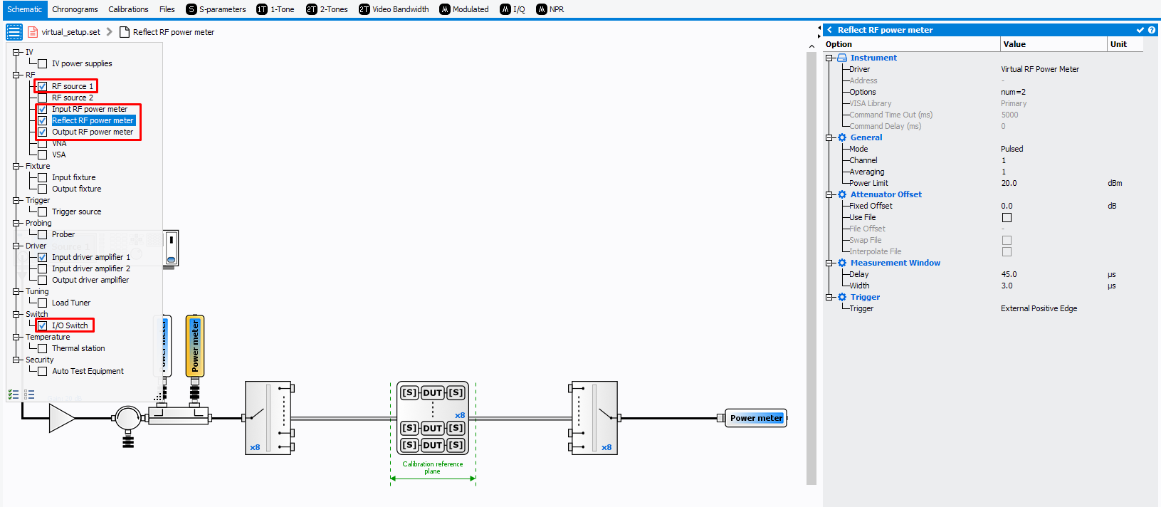
Setup Editor Requirement
The IQSTAR calibration wizard is linked to the
Setup Editor
configuration. In order to get access to the Scalar Power calibration wizard, the
following conditions have to be respected:
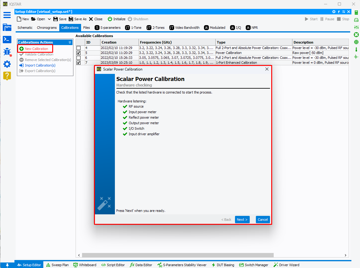
Calibration Wizard
To start a new calibration, select the
Calibrations tab and
click on
New Calibration. The software will verify the communication with
each instrument needed and will configure it using the settings previously
defined.
Once all required hardware is listed, click on ‘Next’.
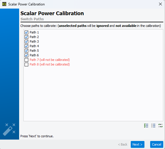
Select the RF
path to calibrate.
Note: Unselected paths won't be calibrated and so not
available during measurement.
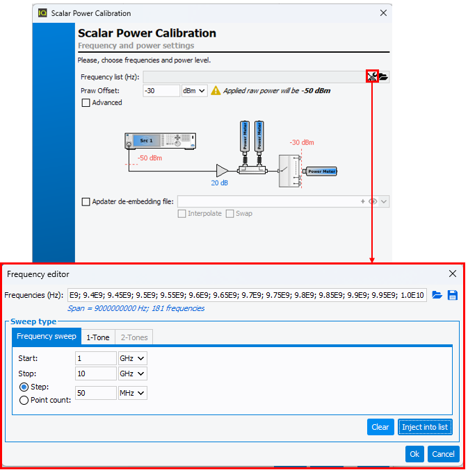
Define the frequency list and the power level to use during the
calibration. The calibration power level should be high enough to get
noiseless and detectable signals measured by the power meters even with the
added attenuators for power sensor protection during the DUT measurents.
This power level should not exceed the power meters limit.
For High Power Amplifier characterization, it is sometime necessary to do a
calibration at a power level that is beyond the limits of the power sensors.
Therefore, it is possible to add, during the calibration, an attenuator to protect
the power sensor. Enter the *.S2P File of the attenuator in the Adapter
de-embedding file field once the box is checked.
Note: This calibration step can be performed in the 'Basic' mode as shown below, but
it also possible to switch to the 'Advanced' mode in order to evaluate the
linearity range of the receiver. To learn more see
Absolute Power Calibration.
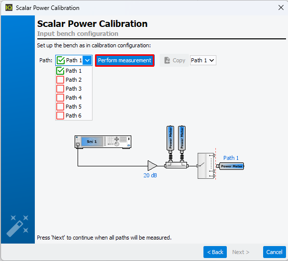
Once the frequency list and the power level have been defined, click ‘Next’.
Then select the first path, and connect the output power meter at the first
input calibration path, to extract the first input factor offset, clicking
"Perform measurement".
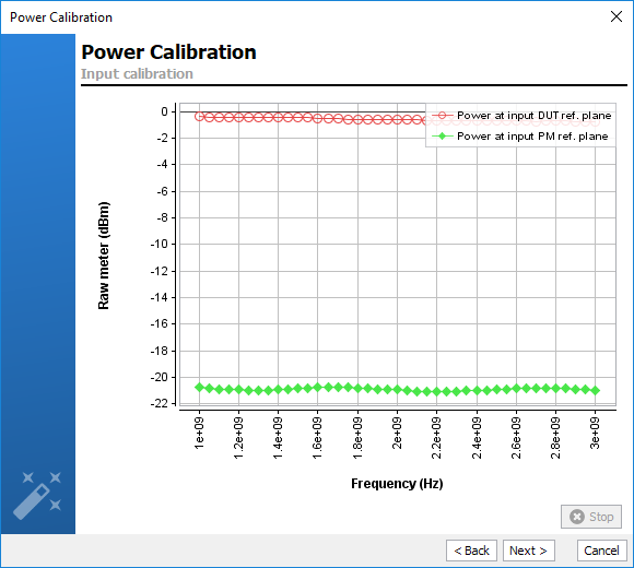
Once the output power meter is connected to the input calibration plane, click
‘Next’ to start the process.
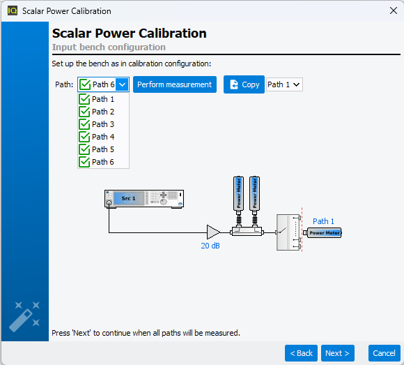
Once first path has been calibrated, use drop-down list to select second path and
force swith matrix to swicth on second path.
This calibration step will be done iteratively for each RF path until all RF path are
done and become "green".
Note: When RF paths are similar, error terms retrieved for a specific path can be
used for other paths using "Copy" button. In this case, the path using
error terms form another path becomes "black".
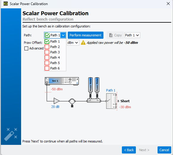
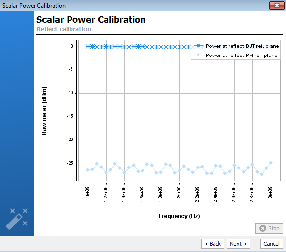
Connect a short at the
input calibration plane, in order to extract the reflect factor offset.
As done for the previous calibration step, refected calibration has to be done
iteratively on each path using the drop down list, selecting the path to
calibrate and pressing "Perform measurement".
Note: This calibration step can be performed in the 'Basic' mode as shown below,
but it also possible to switch to the 'Advanced' mode in order to evaluate
the linearity range of the receiver. To learn more see
Absolute Power Calibration.
Once the
Short (or an
Open)is connected to the input calibration
plane, click ‘Next’ to start the process.
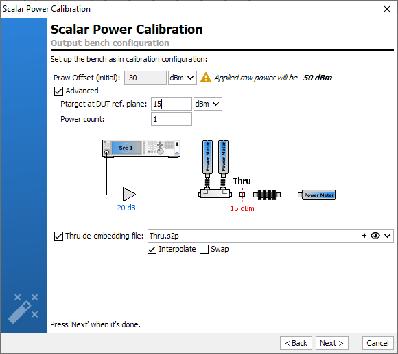
Connect a 'Thru' at the calibration plane and connect the output power meter
after the appropriate output attenuators. The objectif is to extract the output
factor offset. Set the power level at which you desire to calibrate the output
receiver. Setting an appropriated power level for the calibration of the output
power meter is the key of an accurate calibration. Depending on the output power
of the DUT, the external output attenuators added can have a high value (>60dB).
In this case, the power level used during this calibration step should be
sufficiently high to provide noiseless and detectable signals to the output
power meter.
Note: This calibration step can be performed in the 'Basic' mode as
shown below, but it also possible to switch to the 'Advanced' mode in order
to evaluate the linearity ranger of the receiver . To learn more see
Absolute Power Calibration.
In the case where the connectors at the input and output are note insertable,
Male-Male or Female-Female, you need to add an adapter that must
not be taken into account in the calibration. therefore, you can enter the *.S2P
file of the Thru in the Thru de-embedding file field once you check
the box.
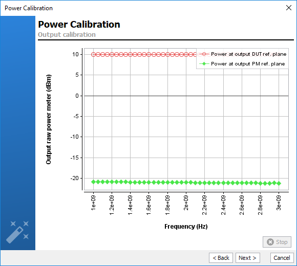
Once the 'Thru' file and the power level have been set, click ‘Next’ to start
the process.
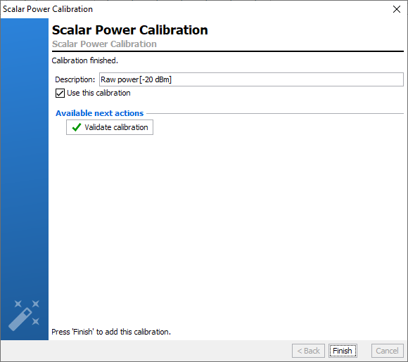
Once the calibration is finished, the error terms are downloaded and recorded
in the
Calibrations tab. A comment is automatically added
but can be modified. This calibration will be used by default for the
measurement unless the box ‘Use this calibration’ is unchecked.
Quick checks can be performed to verify the accuracy of this calibration using
Validate calibration. To learn more see
Validate Calibration.