MultiPath scalar calibration using S-parameters files
Application
Used to correct the power meter measurement to the DUT reference plane. The aim
of this calibration is to determine, without S-parameters pre-characterization,
the offset factor to apply on each power meter to get calibrated measurements.
This Calibration process will help to calibrate the input and output ports when
wideband modulated signal measurements are required:
- 1-Tone Measurements (Pin Available, Pout, Gt, Drain Efficiency, Transducer Efficiency)
- 2-Tones Measurements and Video Bandwidth (VBW) Measurements (Pin Available, Pout, Gt, Drain Efficiency, Transducer Efficiency, C/In, OIPn, ….)
- Modulation Measurements (Pin Available, Pout, Gt, Drain Efficiency, Transducer Efficiency, ACPR, PAPR, CCDF, ...)
- I/Q Measurements (Pin Available, Pout, Gt, Drain Efficiency, Transducer Efficiency, ACPR, PAPR, CCDF, ...)
Note: Vector Signal Analyzer is not mandatory for the
calibration, but should be enabled for 2-Tones Measurements, Video Bandwidth (VBW) Measurements, Modulation Measurements and I/Q Measurements .
Setup Editor Requirement
The IQSTAR calibration wizard is linked to the Setup Editor
configuration. In order to get access to the Scalar Power calibration wizard, the
following conditions have to be respected:
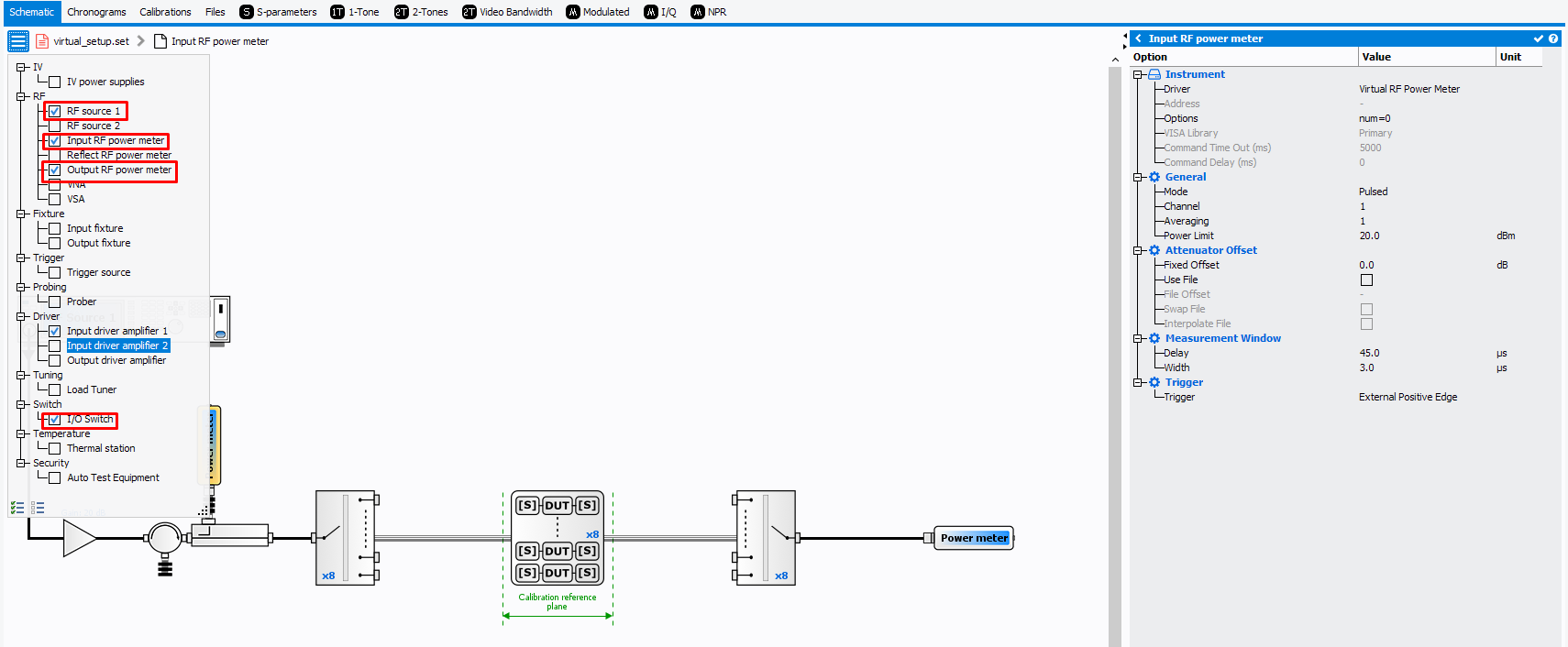
-
A minimum of two Power Meter instruments (input and output) need to be enabled
- One RF Source instrument need to be enabled
- I/O Switch needs to be enabled
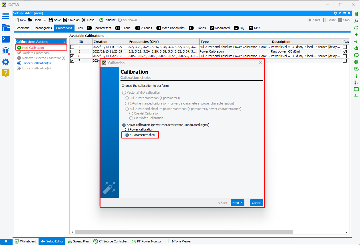
Calibration Wizard
To start a new calibration, select the Calibrations tab and
click on New Calibration. The software will propose to choose between two
Scalar Calibration:
Then select "S-parameters files".
Select the RF path to
calibrate.
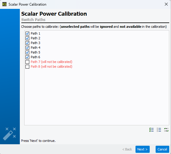
Note: Unselected paths will not be calibrated and so they will not
available during measurement.
Define the frequency list to use during the
calibration.
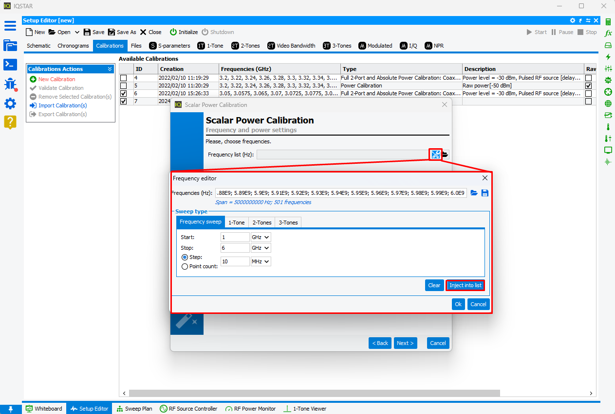
Once the frequency list has been defined, click ‘Next’. Then select the first path, and
define the "direct" and "coupled" s-parameters files needed to describe frequency-wise
input path of first path. Once the first path has been filled in, use the drop-down list
to select the second path and fill in the "direct" and "coupled" S-Parameter files
required to describe the second path's input path. This step will be done iteratively
for each RF path until all RF path are done and colored in black.

Note: When RF paths are similar, the S-Parameters files used for a specific path can
be used for other paths using "Copy" button. In this case, the path using
error will be copied form another path.
Note: If the frequencies defined in
the calibration frequency list are not included in the S-Parameter file, these will
be automatically interpolated.
In case of refected Power Meter use, fill "reflected" S-Parameters file to describe each
refected path. As descrided previously, this step will be done iteratively for each RF
path until all RF path are done and colored in black.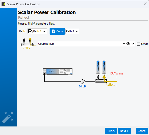
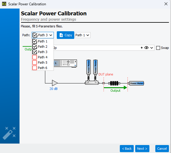
Finally, fill the "output' S-Parameters file to describe each output path. As described
previously, this step will be done iteratively for each RF path until all RF path are
done and colored in black.
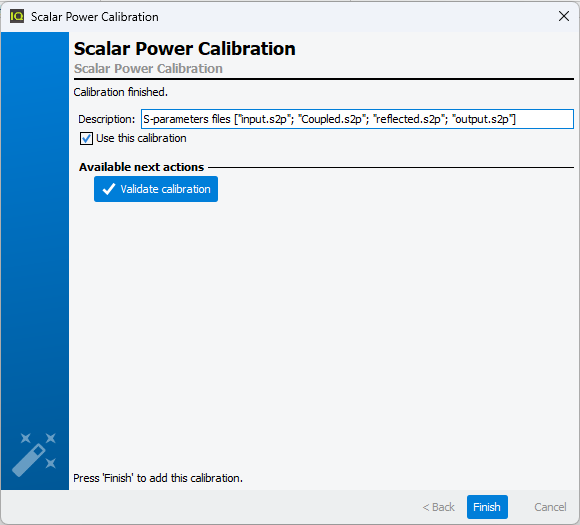
Once the calibration is finished, the error terms are downloaded and recorded in the
Calibrations tab. A comment is automatically added but can be
modified. This calibration will be used by default for the measurement unless the box
‘Use this calibration’ is unchecked.
Quick checks can be performed to verify the accuracy of this calibration using
Validate calibration. To learn more see Validate Calibration.
Note: Contrary to the Scalar Calibration, in Scalar Calibration using S-parameters files the Raw Power Calibration won't be performed automatically.