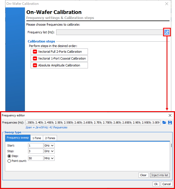
On-Wafer Calibration
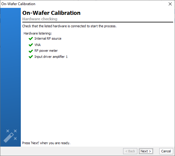
The software will verify communication with each needed instrument and will configure it using the settings previously defined.
Vectorial VNA Calibration
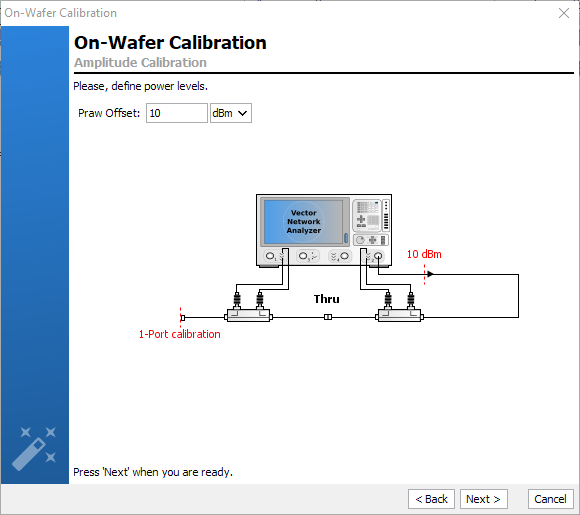
Define the VNA input and output sources power levels to use during the calibration. These power levels should not exceed the maximum power supported by the calibration kit, yet the level should be sufficient to provide noiseless and detectable signals at the VNA receivers even when adding attenuators to keep the receivers safe during the DUT characterization.
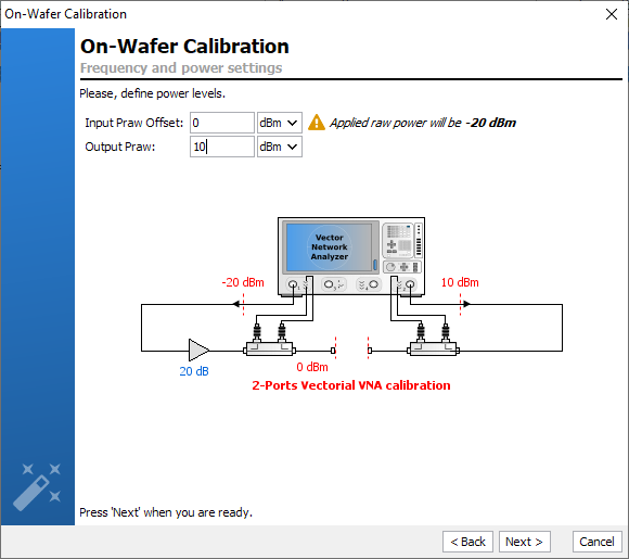
In the example below, DUT has 20W output power and 30dB gain amplifier. The calibration will be performed with the RF source of the VNA set to 0dBm at the input and 10 dBm at the output. Remember that there will be a 30dB attenuator (input) and a 60dB attenuator (output) connected in front of the VNA receivers. To define the appropriated attenuator values on each receivers, see 2) Power Budget.
Once the VNA power level have been set, click ‘Next’.
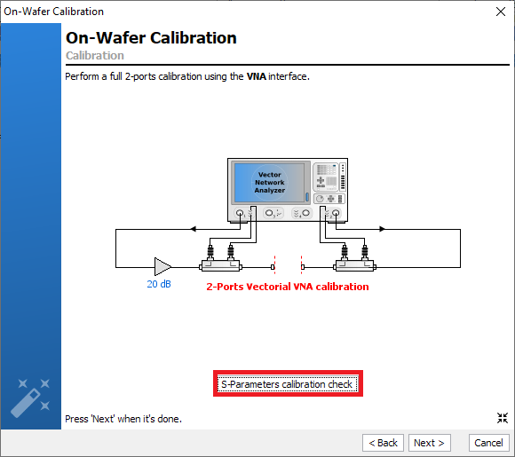
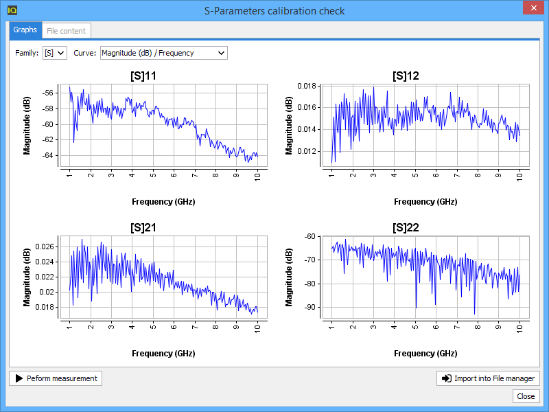
When the calibration on the VNA interface is finished, go back to IQSTAR and press S-Parameters calibration Checkto validate your vectorial calibration or save a 'Thru.s2p' file. Learn more see Validate Calibration.
When the calibration on the VNA interface is achieved go back to IQSTAR and press ‘Next' to continue.
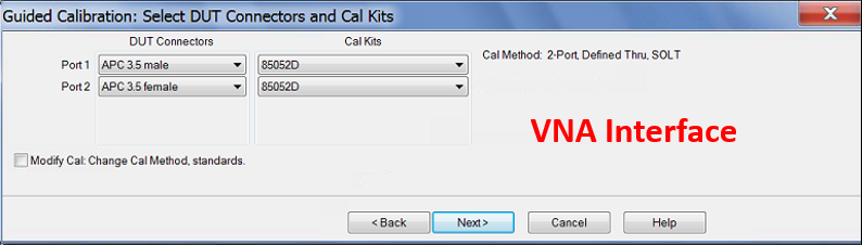
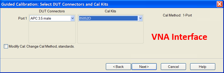
1-Port Coaxial Calibration
- Through the VNA interface
Note: When the VNA's internal couplers are used, it advised to use this interface.
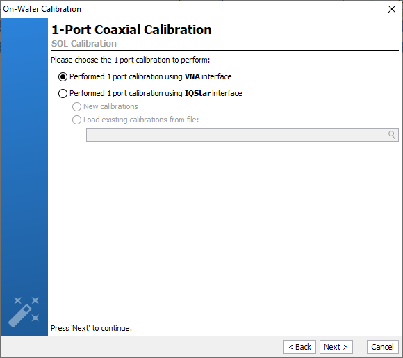
At this step, perform a classic 1-port calibration using the VNA interface.
- Through the IQSTAR interface :

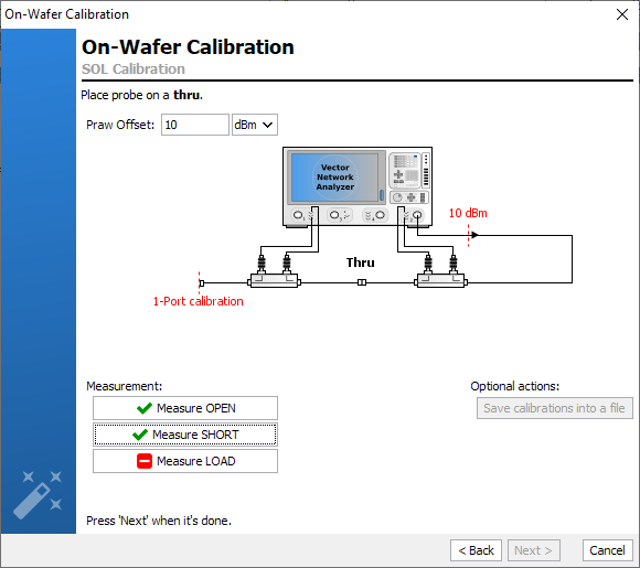
First, define the standards to be used for the SOL calibration. Use the browser to identify the file that contains the standards definitions.

Connect a standard and click on the corresponding button to perform the measurement. Repeat this step for each standard.
Once the SOL calibration is performed, the power calibration can be performed.
Absolute Power Calibration
The power sensor can be eventually zeroed and calibrated before calibrating the absolute power.
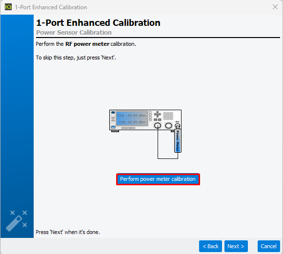
If not, skip this step by clicking ‘Next’.
Then, define the power level used for the absolute power calibration step.
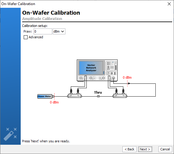
This step allows calibrating the VNA receivers for absolute power measurements using a power sensor as a standard. Setting an appropriate power level for the calibration of the receivers is the key for accurate calibration.
- Basic mode (“No power optimization done”)
In this case, the absolute power error term will be determined on a single power level for each frequency. This calibration method is used when the components of the bench (coupler, attenuator, …) are well-known and already sized to achieve the measurements in the linear range of the receivers.
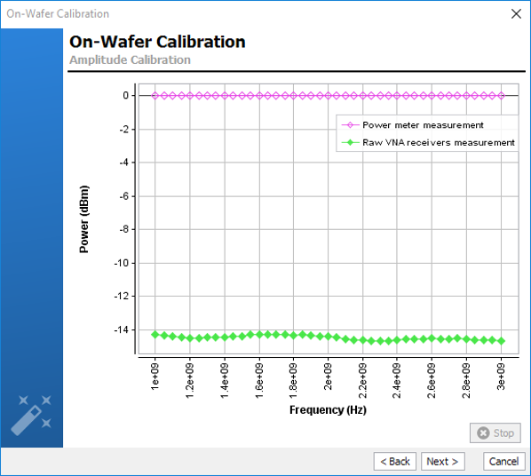
Set the power level at which you desire to calibrate the receivers. The power meter measurements are compared with the receiver measurements in order to determine the absolute power error term coefficient. Using this error term, the absolute power of the RAW data measured by the receiver is corrected. There are several reasons for which you might change these settings:
- The power sensor that is used may have power limitations (typically +20 dBm). However, best accuracy is often close to 0 dBm
- If an external component is used in the measurement path, you MUST adjust
this RF source power setting to compensate for these components. For
example, if you want 0 dBm at the calibration plane and you have a 30dB
amp in the path, you will need to set -30 dBm for this calibration.
Note: If a Driver Amplifier is enabled in the Schematic, the set power level will take into account the Driver Amplifier offset.

-
Note: In the example above, the power meter reading is not constant over frequency. This is due to the dispersive behavior of each passive component (couplers, attenuators, driver amplifier, …). In some configurations, this dispersive behavior can lead the power meter to change its measurement range adding uncertainties to the calibration process. In this case, the advanced mode is advised.
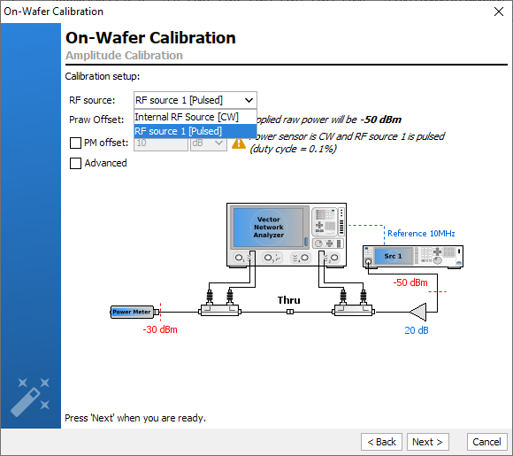
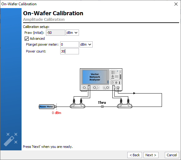
- Advanced mode (“Power optimization done”)
In this case, the absolute power error term will be determined on a power range or on one optimized power level for each frequency. This method is longer than in the basic mode, but it will give also an estimation of the linearity range of the receiver. This calibration method is basically used when the test set bench (coupler, attenuator, …) is not well-known. Therefore, the receiver’s linearity range needs to be checked to evaluate the calibration accuracy.
During this process, the power level of the RF source will be optimized to reach a target value (Ptarget power meter) measured on the power sensor (at the input calibration plane). Then a power sweep will be done from Ptarget power sensor to [Ptarget power sensor– (1dB x Power Count)] in the calibration plane
- Ptarget Power Meter: corresponds to the maximum power level which has to be measured by the power sensor during the power sweep. Note that this level can’t exceed the power sensor limit
- Power count: corresponds to the number of point
of the power sweep. Note that the sweep step is set to 1dB Note: If the Power Count is set to 1, the optimization will be done only at one power level for each frequency.
- Praw Offset (initial) is the initial power
level used during the first iteration of the optimization algorithm.
Note that this power level is linked to the 'Minimum
Power' level set in the RF Source settings. There is a reason that you might change these settings:
- The power sensor that is used may have power limitations (typically +20 dBm). Therefore, the first power level used during the first iteration of the optimization process has to be lower than this limitation to avoid any damages.
Below is an example, where the 'Power count' is set to 1 in order to compensate the dispersive behavior of passive components.

Contrary to the 'Basic' mode, the power level measured by the power meter remains constant over the frequency range, avoiding the change of measurement range of the power meter.
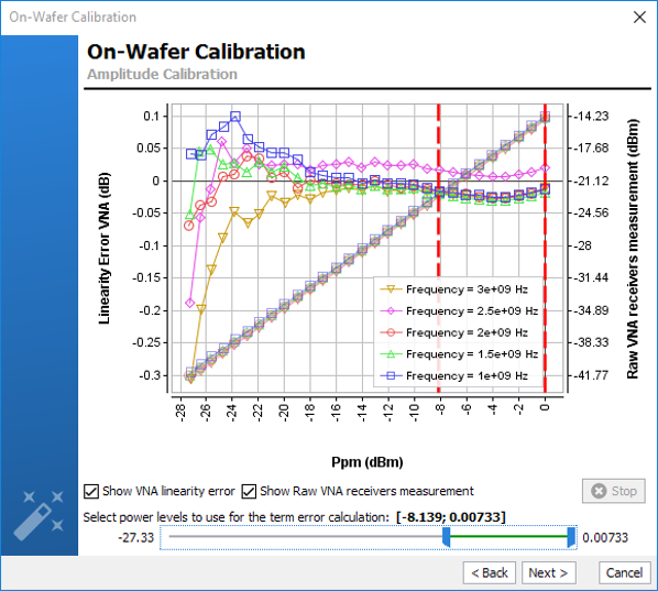
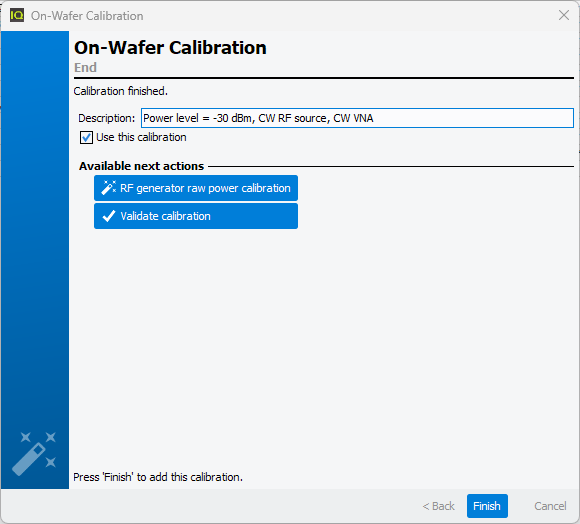
During the calibration process, the RF source level will increase until the power sensor reads the Ptarget power level expected. The process is repeated for each frequency defined in the frequency list (starting from the highest frequency). Once the calibration is completed the error terms are downloaded and recorded in the Calibrations tab. A comment is automatically added but it can be modified. This calibration will be used by default for the measurement unless the box Use this calibration is unchecked.
It is also possible to continue the calibration process by doing a ‘Raw Power Calibration’.Quick checks can be performed to verify the accuracy of this calibration using Validate calibration. To learn more see Validate Calibration.