Tuner Auto De-embedding Calibration
Once the Full 2-Ports & Absolute Power Calibrationcalibration is done, it’s possible to run a Tuner auto-de-embedding wizard.
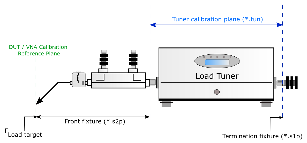
Instead in-situ tuner calibration, this feature allows characterizing the tuner at the tuner’s coax reference plane, and then IQSTAR will automatically generate input and output fixtures files. Using this feature, the tuners do not need to be re-calibrated when a probes/cables/couplers or termination are changed between the DUT and the tuner. Thanks to this unique feature, avoiding unnecessary tuner calibration will save a precious time.
Tuner needs to be characterized at the tuner reference plane (for example) using MTune software. To learn more, see Mtune Characterization Wizard.
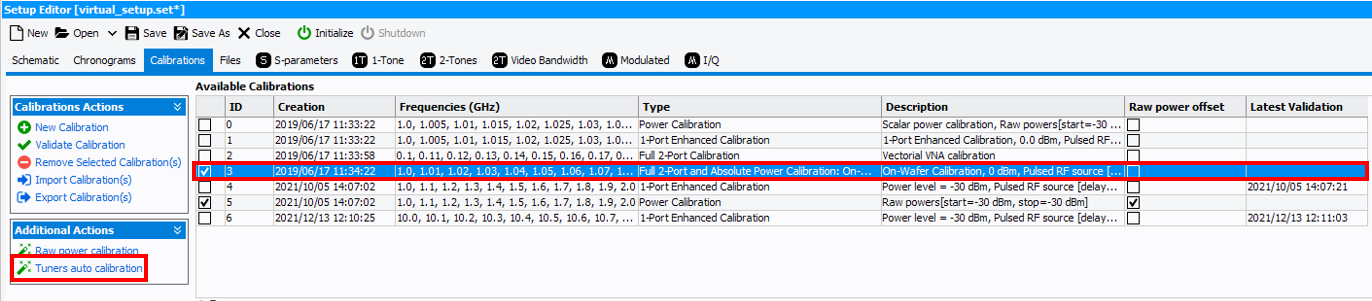
From the “Calibrations” tab, highlight the calibration that was previously done and click on “Tuner auto de-embedding wizard” on the left panel under “Additional actions”.
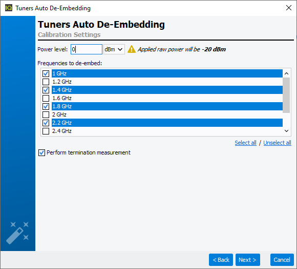
It will check the instruments required to perform the task and verify the connection. Click “Next” if there is a green check on each of the instrument. Next, it will ask to select the frequencies for which the tuner will be controlled. Also enter the power level for VNA source to be used.
Click “Next” and it will show the configuration for the source in order to perform source tuner de-embedding (Leave DUT calibration plane on the THRU during the whole process).
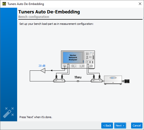
Click “next” once the load configuration is properly setup (50 ohm termination, etc.). It will ask to initialize load tuner if haven’t done so. After the tuners are initialized, the auto tuner de-embedding routines will be executed.
Once the process is done, it will display the maximum gamma available before and after the de-embedding. The blue circle represents the maximum gamma at the tuner calibration plane and the red circle represents the maximum available gamma achievable at the DUT measurement plane.
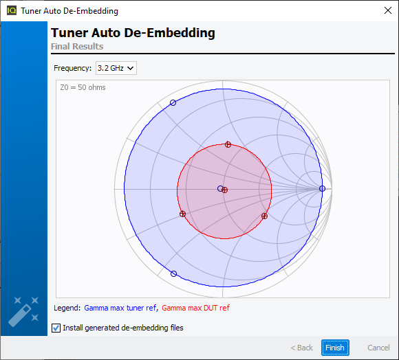
In this example, there is a high loss element placed between the tuner calibration reference plane and the measurement reference plane. The loss is about 3 dB, so the gamma difference is very significant. When the loss between the tuner and the measurement plane is smaller, the maximum gamma will be greatly improved at the DUT reference plane compared to this example.
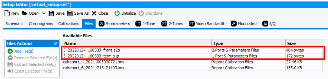
Once the process is finished, it will create 2 files. Click on “Files” and the newly created files will be displayed in the end of the list.
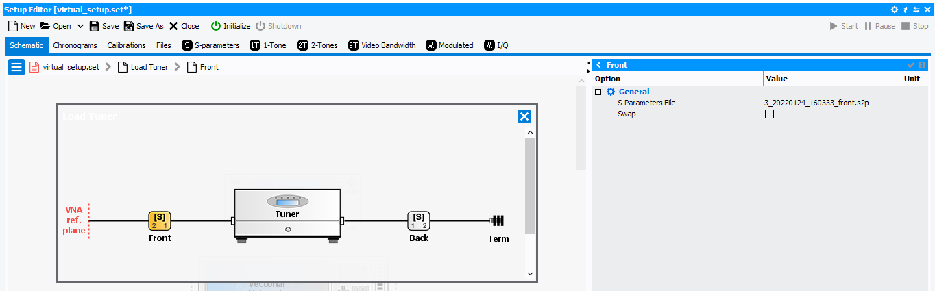
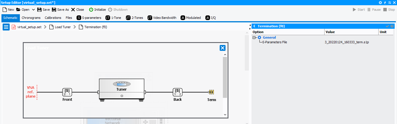
Verify that the files are properly placed in the tuner setup. Click on the Load Tuner icon in the Setup Editor. The Front fixture file and the Termination file will be automatically put in the corresponding fields for proper de-embedding.
Check gamma presented at the DUT reference
Initialize the VNA and calibrate at the probe tip at the fundamental frequencies of the tuner. While touching down on a THRU after the calibration, click on the Load Tuner in the Schematic and click on control to enter to the tuner control dialog.
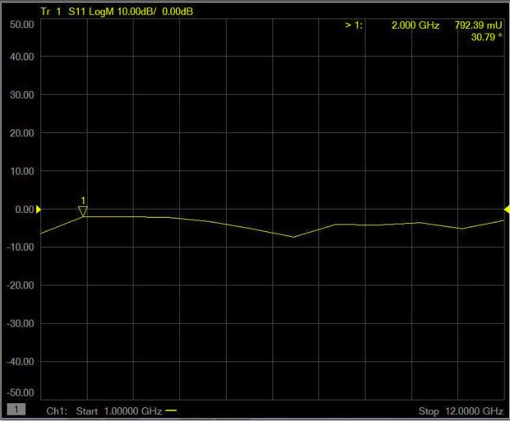
Within the dialog, select the fundamental frequency and enter target gamma (mag=0.8 & phase=30° in this example), and click on “Move”. The load gamma seen at the DUT reference on the load should be mag=0.8 & phase=30°.
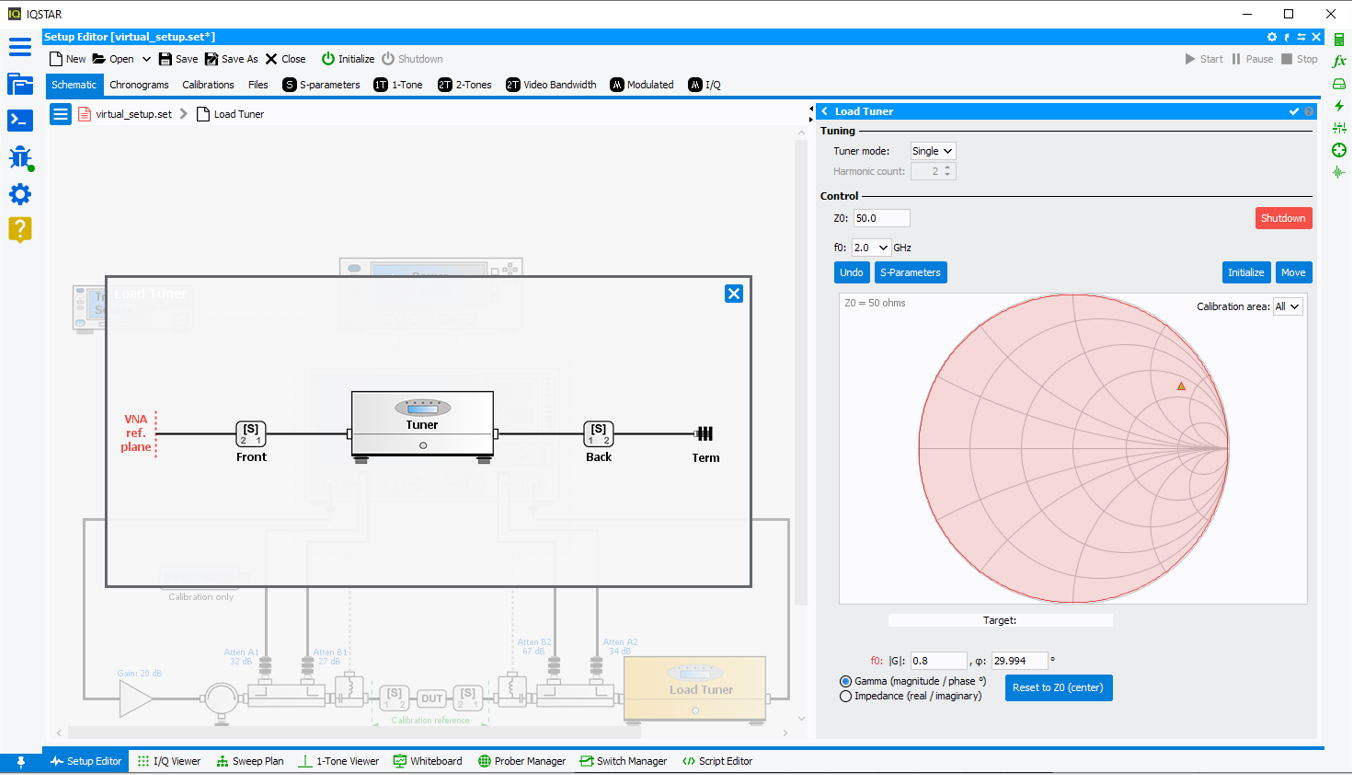
Now verify the gamma at the DUT reference with the VNA. Put a marker at the fundamental frequency of the tuner and put it in linear Mag/Phase format and check if it agrees with the gamma set at the tuner control dialog.