
I/Q Measurement Panel: General
IQ measurement general panel is composed of six sections, to define output file path and name, set measurement stop conditions, define meta-datas ...
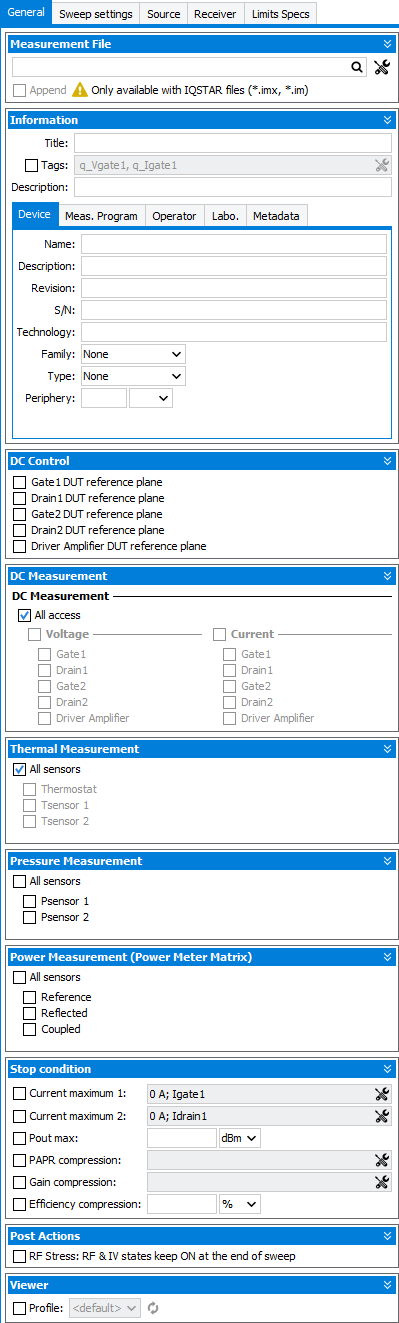
Measurement File:
 . If empty, IQSTAR pops up
a browser at the end of the measurement in order to save the data
. If empty, IQSTAR pops up
a browser at the end of the measurement in order to save the data , is it possible to choose output file format :
"Measurement Files (*.imx)", "Unencryped Measurement Files (*.im)", "MDIF Files
(*.mdf)", "CITI Files (*.cti)" or "CSV Files (*.csv)".
, is it possible to choose output file format :
"Measurement Files (*.imx)", "Unencryped Measurement Files (*.im)", "MDIF Files
(*.mdf)", "CITI Files (*.cti)" or "CSV Files (*.csv)".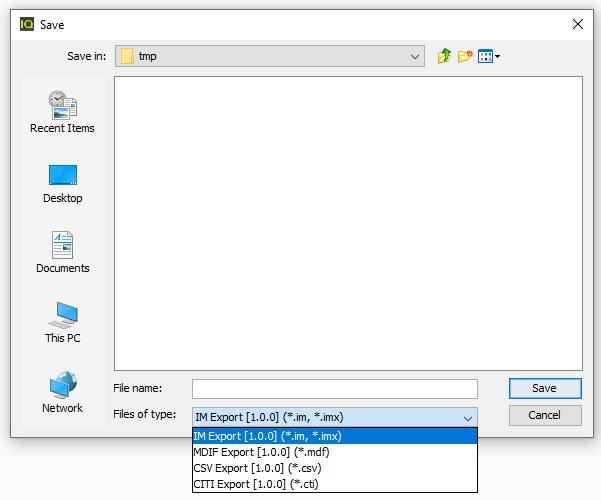
 :
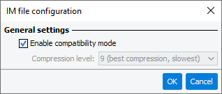
:- for *.im or *.imx files, the interface is the following : IM Export
- for *.csv files, check CSV Export
- for *.mdf files, check MDIF Export
Information:
These information fields will be used by the visualisation and analysis tools in order to filter, sort data or to provide labels, titles or legends. The information entered here is saved in the header of the output file. To learn more see IQSTAR Measurement Files
DC Control:
'DUT reference plane' allows to optimize the DC value at the DUT reference plane through an optimization
DC Measurement:
Thermal measurement
This section is used to define the thermal measurements in parallel to the RF measurements. If some of the sensors are checked, the temperature values will be saved for each measurement point, allowing the visualization of the temperature during the sweeps.
Pressure measurement
This section is used to define the pressure measurements in parallel to the RF measurements. If some of the sensors are checked, the pressure values will be saved for each measurement point, allowing the visualization of the pressure during the sweeps.
Power measurement (Power Meter Matrix)
This section is used to define the power measurements in parallel to the RF measurements. This power measurements are not related to the input or output or reflection power meters, but only to the power meter matrix.
Stop Condition:
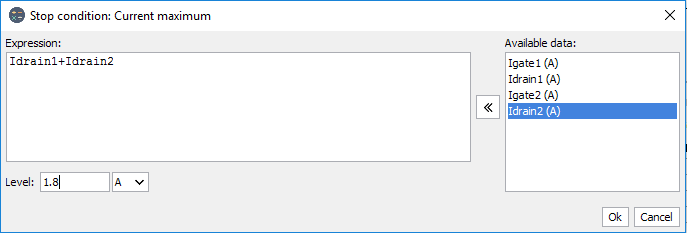
- Current maximum: using set the current limit not to exceedNote: It is also possible to create an expression in order to define a custom figure of merit (e.g. sum of two currents).
- Pout max: set the limit of output power of the DUT
- PAPR Compression: using set the limit in PAPR compression if the
reference is the maximum PAPR or the linear PAPR (it's also possible to
average the linear part by setting point count) and finally set the level in
dBNote: In the general panel of modulated measurements, there is one more stop condition based on the Peak to Average Power Ratio (PAPR) compression. Indeed, as the main receivers (Power Meter) are wideband, the basic gain compression stop conditions will work on the average power. In order to base the stop condition on the peak power, it's advise to add a stop condition on the PAPR compression. To get access to this feature, the CCDF measurement should be enabled.
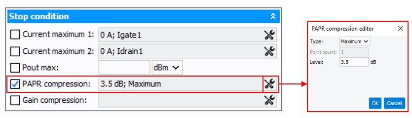
- Gain compression: using set the limit in gain compression (Transducer
or Power gain) if the reference is the maximum gain or the linear part (it's
also possible to average the linear part by setting point count) and finally
set the level in dB
Post actions
- RF Stress: RF & IV states keep ON at the end of a sweep: used to keep
the RF and IV on after the end of a sweep, allowing the DUT to stay biased and
under stimulus.Note: This option can be used to stress the DUT and see how the performances are affected in time. By shutting down the bench, the RF and IV will be automatically forced off.
Viewers
Allows to define a specific Real time viewer profile when new measurement is started. (useful during a Sweep Plan).