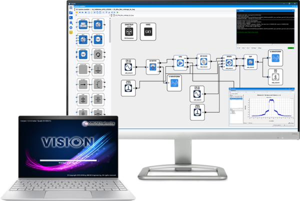


April 07, 2024: VISION 2.4.1 Software Release
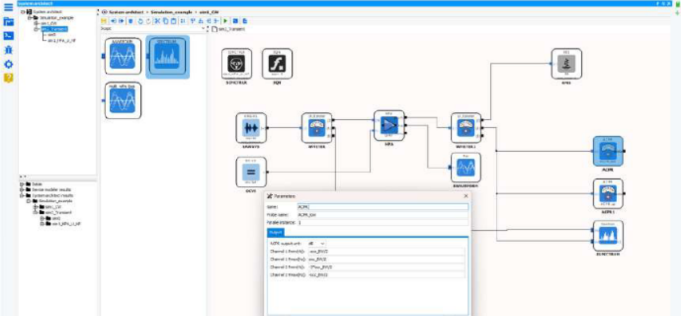
Unveiling new possibilities, VISION version 2.4.1 empowers engineers with unparalleled capabilities to enable the future of their system design. From intricate circuit designs to cutting-edge RF systems, VISION transcends boundaries, delivering a seamless bottom-up realistic simulation capability of microwave circuit architectures.