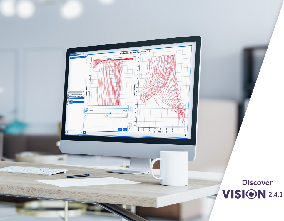
AMCAD Engineering has announced the release version 2.4.1 of VISION, Introducing the next evolution in electronic circuit modeling and RF system simulation tools.
Unveiling new possibilities, VISION version 2.4.1 empowers engineers with unparalleled capabilities to enable the future of their system design. From intricate circuit designs to cutting-edge RF systems, VISION transcends boundaries, delivering a seamless bottom-up realistic simulation capability of microwave circuit architectures.
This release includes new modules and features to address the industry’s additional Modeling and simulation requirements. It also showcases enhancements of the capabilities of the existing modules to improve user experience.
VISION 2.4.1 Main New Features and Software options
New Linear Parametric Model to simulate tunable RF filters
RF tunable filters find applications in various fields where precise frequency control and filtering are required. Some common applications include:
- Wireless Communication Systems: RF tunable filters are used in wireless communication systems such as cellular networks, WiFi, Bluetooth, and satellite communication systems to select specific frequencies and reject unwanted signals, thereby improving signal quality and reducing interference.
- Radar Systems: In radar systems, RF tunable filters are employed for frequency agility, allowing radar systems to adapt to changing environments and frequencies. They help in filtering out unwanted signals and interference, enhancing the radar’s performance.
- Electronic Warfare (EW): RF tunable filters are crucial in EW applications for signal processing, frequency hopping, and jamming suppression. They enable the selective filtering of signals of interest while attenuating or blocking interfering signals.
- Military Communication Systems: Military communication systems utilize RF tunable filters for frequency hopping, spectrum spreading, and selective signal reception. These filters enhance the security and reliability of communication in hostile environments.
- Medical Devices: RF tunable filters are used in medical devices such as MRI machines and wireless medical telemetry systems. They aid in selecting specific frequencies for data transmission and reception, ensuring accurate and reliable medical diagnostics and monitoring.
- Test and Measurement Equipment: RF tunable filters are essential in test and measurement equipment for spectrum analysis, signal generation, and frequency response testing. They enable precise frequency selection and filtering, ensuring accurate measurement results.
- Aerospace and Defense: In aerospace and defense applications, RF tunable filters are utilized in radar systems, electronic countermeasures, satellite communication systems, and avionics. They help in achieving high-performance communication, navigation, and surveillance capabilities.
Overall, RF tunable filters play a critical role in a wide range of applications where precise frequency control, signal filtering, and interference rejection is essential for optimal system performance.
Our customers have asked us to push back the boundaries of simulation of complex RF chains in which tunable filters are used. Their impact on signal integrity across different building blocks needs to be assessed by careful design examination.
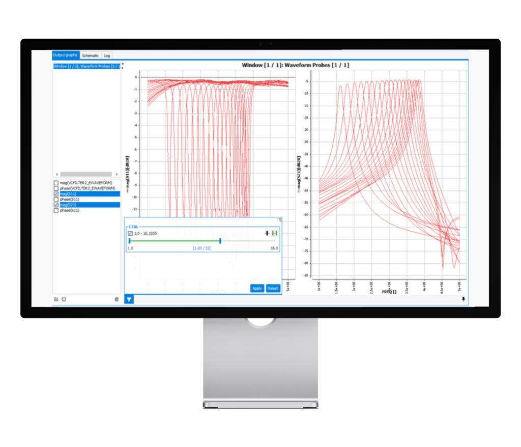
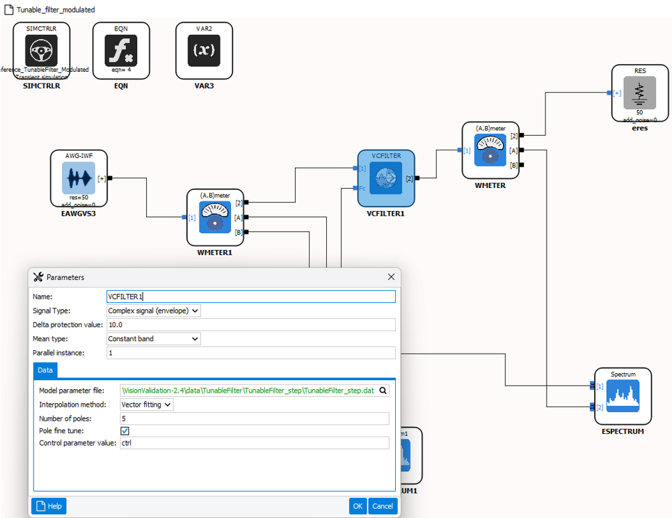
In this example, it can be seen that voltage control shifts the center frequency of the narrow-notch filter. In the previous version of the Vision software, this type of circuit was available in the simulation model via a parametric block of S parameters.
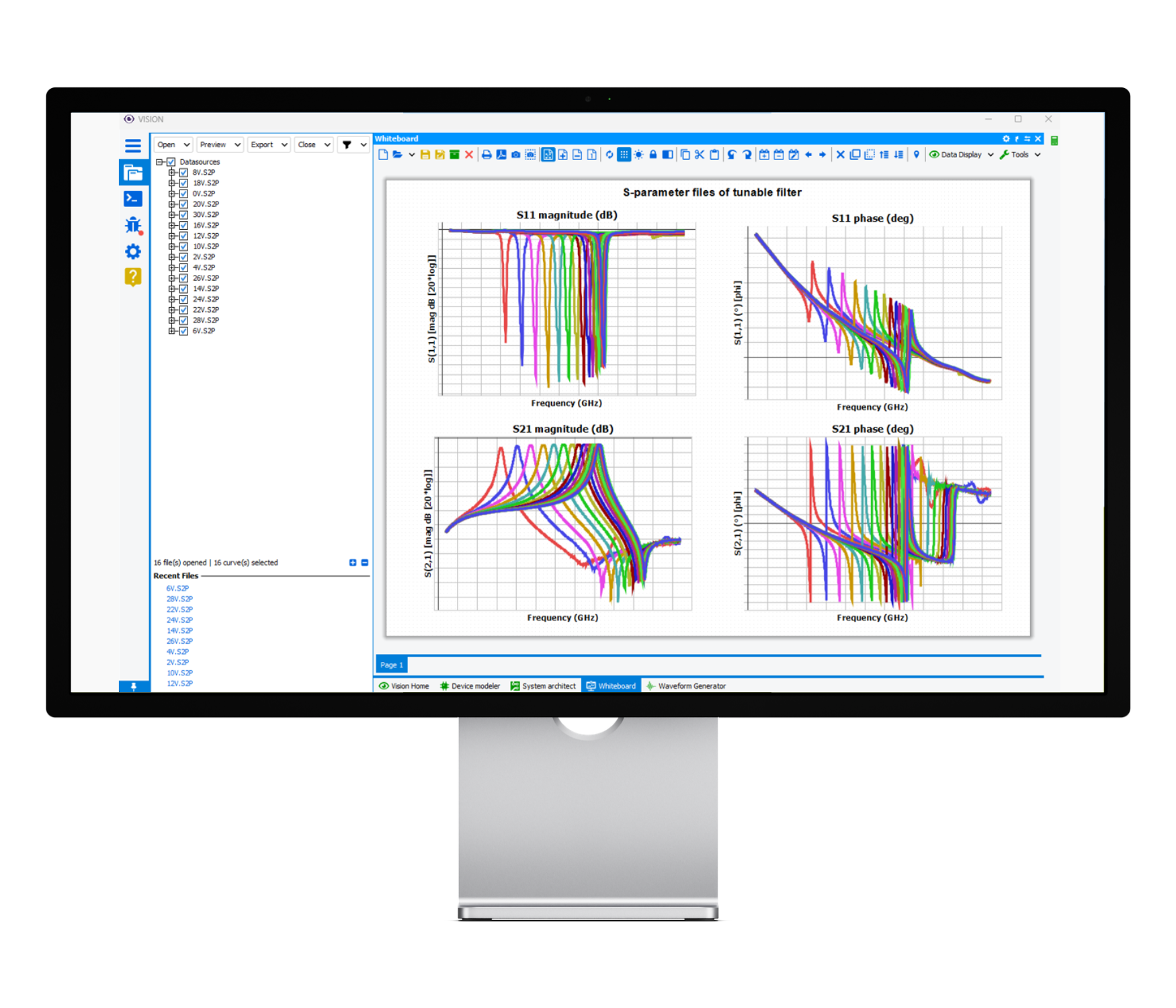
The data supplied to extract the model consists of a text file containing the parameters scanned, and the names of the various elementary S2P files (one file per parameter value). The aim is to simulate the filter response, for different values of the parametric control, which can be an interpolated value of the input data. The difficulty is to manage the frequency response of the interpolations, so as to avoid the filter’s frequency response highlighting artificial ripples.
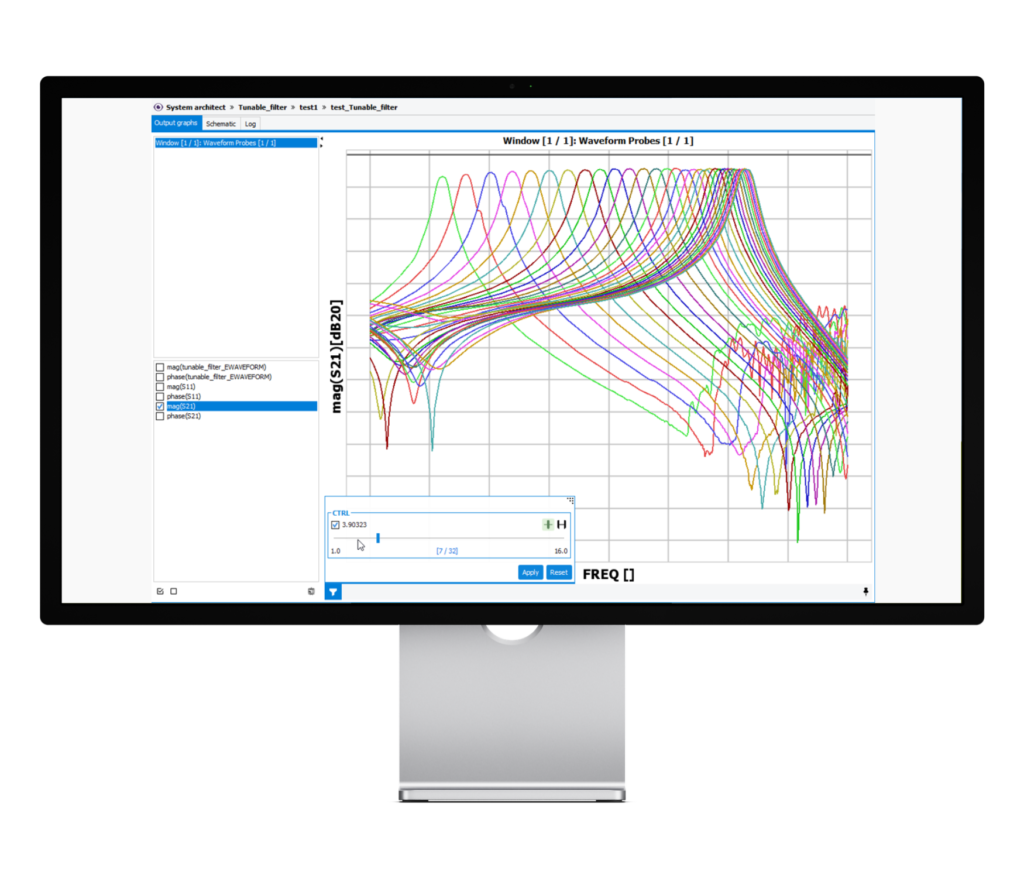
Thanks to a specific modeling technique, the new version now offers smooth interpolated frequency responses, even for interpolated S-parameter responses, to ensure accurate simulations or RF chains with modulated signals.
Parametric models of the SnP or tunable filter type can be used to model an ad hoc network. In this type of structure, optimizations are complex because all frequencies can be used, and mismatching effects due to active elements are numerous.
A challenge in complex ad hoc networks with multiple tunable filters is to be able to calibrate these systems via an algorithm based on the number of commands and operating frequency values. Thanks to these models used in CW mode, the development of these calibration functions is now possible.
Vision offers then a powerful solution to simulate the broadband behavior of a passive dipole whose tuning frequency varies.
This time-frequency representation allows the user to verify the performance of his system after determining a calibration law in face of modulated signals.
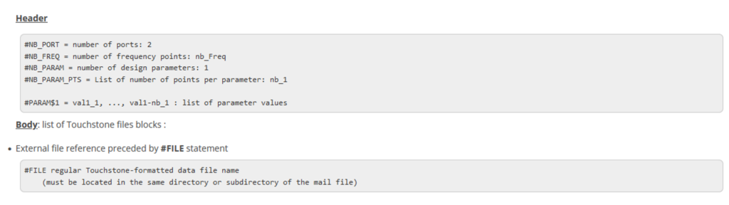
The manipulation of such a model is very simplified because the GUI handles a list of measurement files (i.e. s2p file) in Touchstone format via a simple configuration file with the following data:
This time-frequency representation allows the user to verify the performance of his system after determining a calibration law in face of modulated signals.
WFG100-31 Waveform Generator : Noise to Power Ratio (NPR) Signal Generation
The NPR generation module, WFG100-31, is embedded in the System Architect (VIS100-E) and aNoise to Power Ratio (NPR) simulation is crucial in RF system simulation for space communication, for various scenarios where the assessment of noise performance is essential.
- Receiver Design: In the Design of RF receivers, understanding the Noise to Power Ratio is critical. It helps in evaluating the receiver’s sensitivity, which is the minimum input signal power required for the receiver to achieve a specified level of output signal-to-noise ratio (SNR). NPR Simulation helps designers optimize receiver parameters such as gain, bandwidth, and noise figure to achieve the desired performance.
- Amplifier Characterization: For RF amplifiers, NPR simulation is necessary to evaluate the amplifier’s noise figure and gain under different operating conditions. By simulating NPR, designers can analyze how amplifier parameters, such as biasing, matching networks, and operating frequency, affect noise performance.
- Communication System Performance: In communication system simulations, NPR analysis helps in assessing the overall system noise performance, including contributions from transmitters, receivers, amplifiers, and other components. Evaluating NPR allows designers to optimize system parameters to achieve the desired signal quality and minimize the impact of noise.
- Frequency Planning and Optimization: NPR simulation aids in frequency planning and optimization for RF systems, particularly in crowded or interference-prone environments. By analyzing NPR at different frequencies and bandwidths, designers can identify optimal frequency bands and channel allocations to minimize noise and maximize system performance.
- Satellite and Wireless System Design: In satellite communication systems, wireless networks, and other RF applications, NPR simulation is essential for predicting system performance in the presence of noise sources such as thermal noise, intermodulation distortion, and external interference. Designers can use NPR analysis to optimize system parameters and configurations to meet performance requirements.
Overall, NPR simulation is essential for RF system design and optimization, providing information on noise performance and enabling engineers to make informed decisions to achieve optimum system performance and reliability.
The NPR generation module, WFG100-31, is now integrated into the system architect (VIS100-E), and enables simulation of an ultra-wideband signal used for characterization of satellite communication systems.
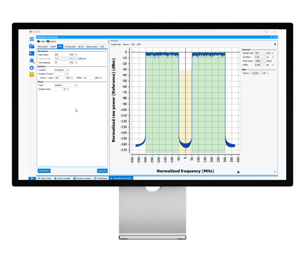
The NPR-type signal generation can be customized to define the signal bandwidth, as well as the number and location of notches in the signal.
The system architect uses the generator to inject the signal for simulation, and IQ probes to demodulate the amplified signal to calculate the noise power ratio (NPR), to illustrate the linearity of the system.
WFG100-11 & WFG100-12: LTE and 5G NR Waveform Generation and Demodulation
The 2.4.1 release of VISION has been updated with new modules:
- WFG100-11 for LTE signal generation and demodulation
- WFG100-12 for 5G NR signal generation and demodulation.
The waveform generator includes the same functionality as the IQSTAR measurement software, for adjusting user-defined signal parameters. The signal can then be exported to a file and used for simulation.
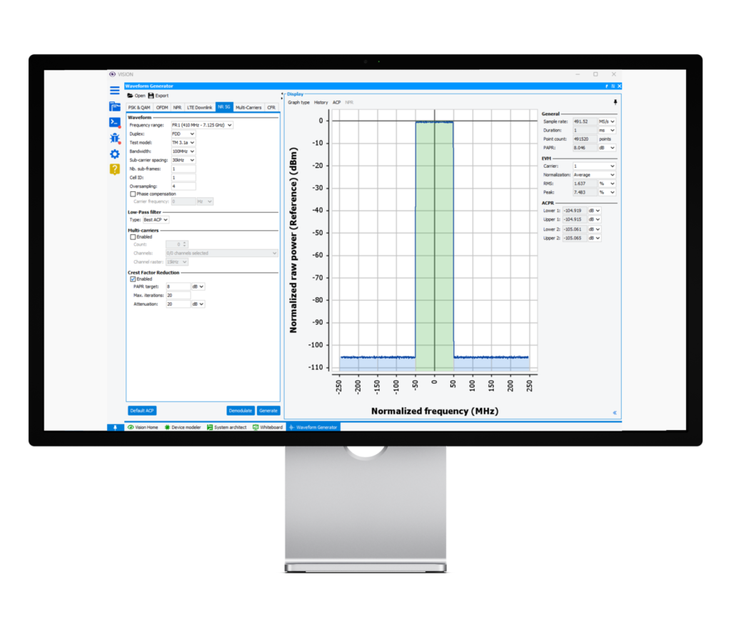
The demodulation algorithm calculates various factors of merit, such as EVM, and displays the signal constellation for easy comparison of simulation and measurement results, without the need for time-consuming post-processing. This simplified post-processing process has been added for OFDM, NPR, LTE and 5G signals.

The waveform generator module included in the system architecture module (VIS100E) takes advantage of IQSTAR-VISION’s cross-platform software compatibility to ensure a smooth, consistent approach in the worlds of measurement and simulation.
This new module makes it possible to evaluate in simulation the key performances of modern telecommunication systems, such as EVM and BER. The 2.4.1 release of VISION shares similar plug-ins with IQSTAR software for circuit characterization. Indeed, the waveform generator can run on both platforms, enabling test signals to be generated. These signal files can be imported or exported between the measurement and simulation platforms to ensure high quality model validation.
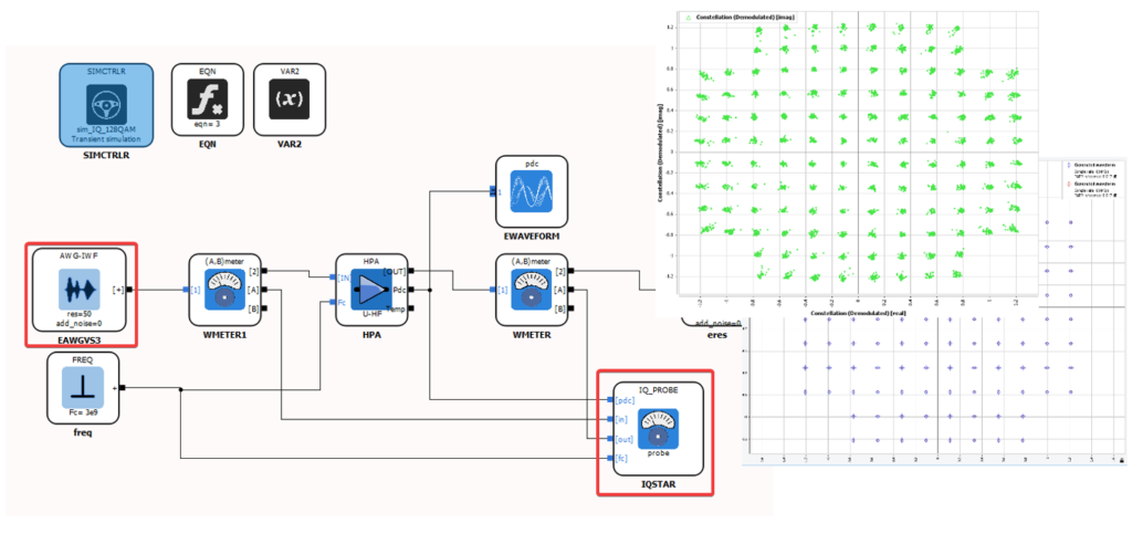
The diagram editor provides a signal source for importing an iwf file generated by the Waveform Generator application and the IQSTAR IQ-probe for demodulation and analysis. Simulation results are formatted so that they can be easily compared with IQ validation measurements made with IQSTAR software..
HPA-B-HFTH model extraction using data provided by circuit Simulators
VISION 2.4.1 provides advanced functionality for extracting high-frequency and thermal bilateral models (HPA-B-HFTH) from simulation data, using results from circuit simulators such as Pathwave ® ADS provided by Keysight Technologies.
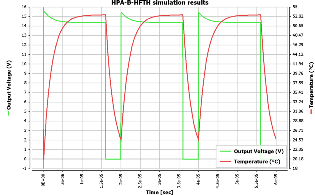
VISION 2.4.1 includes specially designed templates to help users extract the necessary data efficiently. This development is based on a new approach, incorporating a feedback mechanism that combines an electrical model with a thermal cell. This integration is essential for understanding the effects of self-heating and its impact on RF performance, a factor of vital importance in system design and optimization.
The usefulness of this model extends to various applications, notably in RADAR systems using pulsed signals, where pulse envelope variation is partly linked to PA’s self-heating phenomenon.
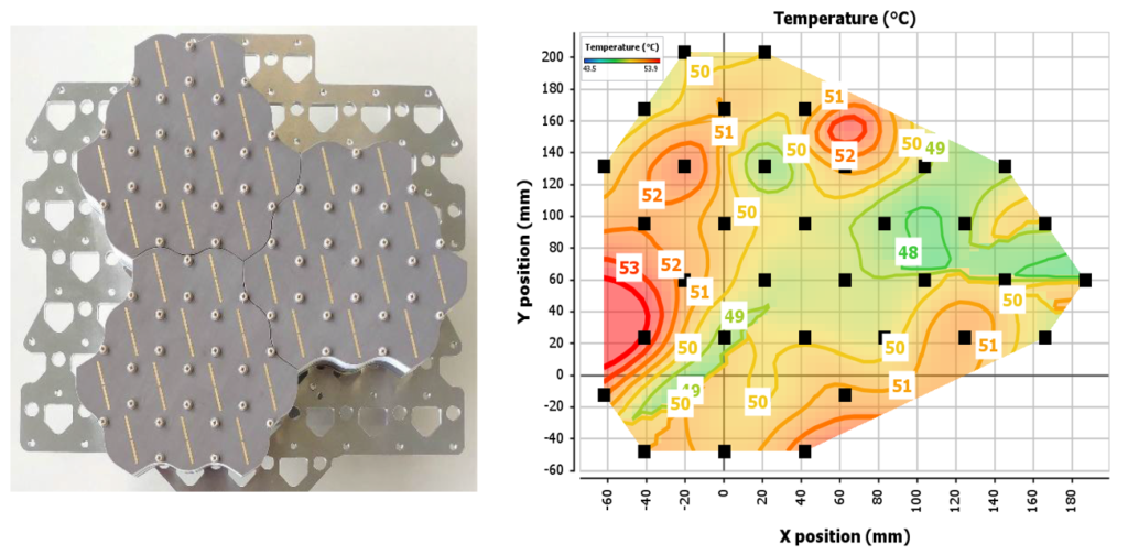
This functionality is particularly intended to improve the reliability and performance of these systems, by providing a more in-depth thermal analysis capability, for example in the analysis of active antenna systems to locate hot spots influenced by the positioning of power amplifiers in the system..
Simulation results for active antenna systems based on VISION’s HPA-B-HFTH model can be used to analyze the temperature fluctuation of PAs due to self-heating as a function of the location of each PA in the antenna, and as a function of operating conditions such as steering angle, carrier frequency or system input power. These simulation results can be used by thermal engineers in third-party thermal simulators to evaluate heat dissipation through the antenna’s physical structure, and thus establish thermal management strategies for the entire system..
Multiblock Feature
When dealing with block diagrams of increasing size and complexity, an effective approach is to structure them into more manageable units, called multiblocks. A multiblock is a block in a diagram that encapsulates a specific subset of blocks. Within a single diagram, several multiblocks can be incorporated, and multiblocks can be nested within each other to provide additional organizational depth.
Using Multiblocks to manage function diagrams offers significant advantages, including
- Hierarchical Organization: Blocks are arranged in layered structures, facilitating deeper navigation.
- Functional Grouping: Functionally related blocks are grouped together, enhancing coherence and understandability.
- Diagram Simplification: The display of the diagram is streamlined by minimizing the number of visible blocks in the main window.
- Defined Interfaces: Clear interfaces with specific inputs and outputs are established, improving integration and interaction within the block diagram.
VISION 2.4.1 Main Improvements and bug fixes
Numerous improvements and bug fixes have been made to enhance the user experience.
- Import of IMX files is no longer limited to PSK and QAM
- Simulation controller export tab improved.
- Default signal unit value is set to dBm in Awg an awg-iwf sources.
- Removed CCDF percent in the receiver panel.
- PAPR in f0 level using max / mean algorithm in the post processing.
- New template schematic added:
- “Parameterized SNP” template to run model of 3-port switch controlled by a parameter value
- “Tunable filter” template to run model of bandpass filter which center frequency is controlled by voltage parameter value
- The “Port Number” in the source CW and Epulse is replaced by “Port rank” to match the other.
- Fixed an issue where the demodulation post process erased the simulation imx when using a IWF source without IQProbe.
- Fixed an issue in Simulation Controller where Noise Analysis option was tested even when not available in license causing a crash of the application.
- Harmonization of option parameters between HPA-B-HFLF & HPA-U-HFLF Model
- Fixed Extractor bugs when using ADS File format for HPA_U_HFLF model on Linux.
- Fixed issues where the extraction results were not loaded properly when bilateral order is 0 with HPA-B-HF and LNA-B-HF models.
We would like to thank our growing number of customers for their feedback, which helps us to improve VISION with each new release. A more detailed list of all new modules, features, enhancements, drivers and bug fixes can be found in the VISION product manual, available with the software installation program.