Why RF Vector Signal Transceivers are getting popular?

An RF Vector Signal Transceiver is an instrument that can transmit and receive RF signals. They are used in a variety of applications, including wireless communication, radar, and test and measurement. Some of the benefits of using such an instrument include:
- Versatility : RF vector signal transceivers embed both a signal generator and an analyzer, they can operate over a broad-spectrum of frequencies and bandwidths, making them suitable for use in a variety of applications.
- Accuracy : They have a high dynamic range, which allows them to accurately capture and reproduce signals for various phases, frequencies, and amplitudes, for high-precision measurements.
- Speed : Many RF Vector Signal Transceivers are designed to operate in real-time operation, allowing fast and accurate analysis of baseband RF modulations.
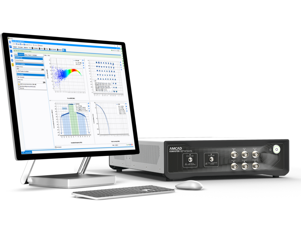
- Control : They can be remotely controlled by a software application like IQSTAR, allowing users to easily perform complex measurements for deep analysis
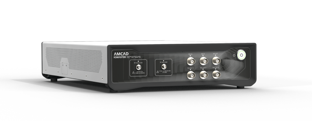
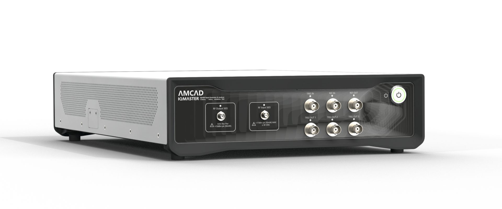
Discover the unique advantages of using the AMCAD IQMASTER 6400

High-end RF Vector transceivers can be found on the market, with excellent hardware specifications. Nevertheless, based on our customer’s feedback, major road blocks are still observed. Below are some examples of issues which prevent the widespread use of VST in the labs.
- Issue n°1 : Having a VST with outstanding specifications is fine, turning this one into a measurement instrument which can be easily integrated into an existing measurement bench can be difficult.
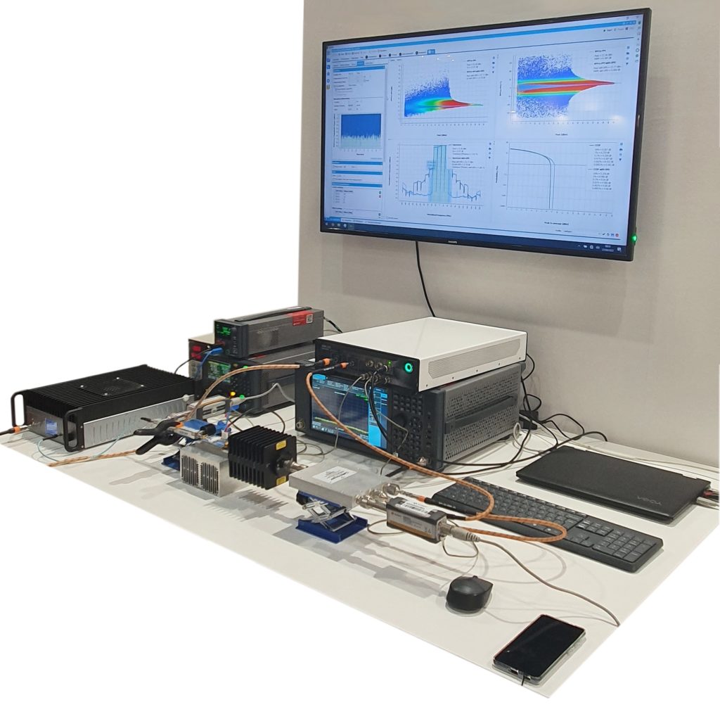
- The IQMASTER 6400 Vector Signal Transceiver is a solution which can be driven by our IQSTAR software application, as a plug and play solutions, from basic test needs (such as pulsed one tone, two-tone measurements), up to more advanced configurations (such as Digital Predistortion measurements).
- Issue n°2 : Our IQSTAR controlling software can also drive high-end signal transceivers provided by other manufacturers, but a Power Amplifier vendor must prove that its power amplifier will meet some target specifications in a real-world environment, such as Radio Remote Head (RRH) of a base station, for example.
- The IQMATSER 6400 solution is made of RF components that are natively developed for RF telecommunication systems. If an amplifier can be driven with this solution, the same RF transceiver components can be set around the PA in the RRH to provide the performances which have been previously observed into the lab.
- Issue n°3 : High-end instruments can be expensive, preventing them from being deployed on a large number of benches to accelerate the test.
- While one high-end instrument can be used as a reference, our IQMASTER solution can be easily benchmarked, and be then deployed on different test stations to save some CAPEX and expand the number of benches that will work in parallel.
AMCAD use RF components on the shelf, primary developed for RF base stations, and turn them into measurement instruments. A high-end software measurement application is added on top, to provide our customers a premium measurement experience. This allows our customers to use solutions that are easy to handle, with the latest generation of VST SoC used in base stations.

ASK FOR DEMO LOANER
Please fill out the following form with your details to initiate the rental process
Pulsed RF measurements
There are several steps involved in performing pulsed RF measurements:
The IQMASTER 6400 can be used as a cost affordable measurement equipment for this application. This one can play different IQ files to generate pulsed signals at a desired frequency, pulse widths, and amplitudes. The RF vector signal transceiver can then transmit the pulse and capture the pulse response of the device under test. The measurement software IQSTAR can then analyze the response and extract relevant information, such as the pulse output power, gain, efficiency, and other parameters. It is important to carefully calibrate the measurement equipment and follow proper measurement techniques to ensure accurate and reliable results.
Adjacent Channel Leakage Ratio (ACLR) Measurements
The adjacent channel leakage ratio (ACLR) is a measure of the amount of power leaking from a specific channel into an adjacent channel. This one is typically expressed in dBc (decibels relative to the carrier). To measure ACLR on a radio frequency (RF) power amplifier, the following equipment is generally needed (A signal generator with modulation capabilities; a spectrum analyzer, power meters and accessories, such as directional couplers, loads, etc.). The VST IQMASTER 6400 can be advantageously used to replace the generator and the spectrum analyzer. The IQ signal measured in the time domain can be converted in the frequency domain using a Fast Fourier Transform (FFT) to obtain the equivalent spectral shape and measure the ACLR.
Dynamic AMAM and AMPM measurements and Digital Predistortion (DPD)
Dynamic Amplitude-Modulation-Amplitude-Modulation (AMAM) and Amplitude-Modulation-Phase-Modulation (AMPM) measurements are used to characterize the nonlinear behavior of a radio frequency (RF) power amplifier.
The AMAM and AMPM can be represented by nonlinear continuous curves when the power amplifier is driven by one-tone signal (one frequency). When, the carrier is modulated in magnitude and phase, the continuous AMAM and AMPM curves are replaced by a cloud of points. This phenomenon is caused by the memory effects that takes place in power amplifiers. Indeed, the output signal is no longer only a function of the input signal. This one is also driven by the past signals (T-1, T-2, …T-n) that influence the instantaneous behavior of the device under test. This can be caused by high-frequency memory effects (such as the distortion of the modulation caused by the response of the matching circuits at the carrier frequencies for example), and by low-frequency memory effects (long time constant due to the thermal behavior of the device, or trapping effects that can take place in GaN transistors).
Digital predistortion is a technique which is used to compensate for the nonlinear behavior of RF power amplifiers. It involves applying a predistortion function to the input signal in order to cancel out the distortion that will be introduced by the amplifier. This allows the amplifier to operate more efficiently and with less distortion. Digital predistortion can be implemented either in specific algorithms played by the controlling software of the measurement instrument as IQSTAR (software based DPD), or implemented using digital signal processing algorithms directly coded into the hardware, such as a field-programmable gate array (FPGA).

