Why do we need a Power Amplifier Stability Analysis ?
RF components with feedback structure can be prone to stability issues when supplied with an input RF signal, a DC bias or a load impedance. When designing a Power Amplifier, attention must be paid to multiple details to minimize the risk of oscillation. The PCB layout, the basic structure of the transistor, the wiring and much more factors can have a direct or indirect effect on the stability of the circuit.
Stability analysis of Power Amplifiers is mandatory to ensure proper behaviour when supplied with an RF signal, terminated with a certain load impedance or biased in a certain DC condition. The oscillation effects can cause permanent damage to the Power Amplifier or at least reduce its life span without mentioning the effects on the performance of the overall system in which it is embedded.

First pass design is an objective that all companies try to achieve. On the one hand, time to market and cost of production requirements tend to limit the number of design iterations the product needs to go through. On the other hand, the stability of a power amplifier is a phenomenon that delays production, as oscillations cannot always be predicted during simulation. Therefore, using the proper tool to predict and correct oscillation issues is a must.
Rollett’s, K and μ factors
Rollett’s, K and μ factor are methods widely used in commercial CAD simulators. These techniques are valid in small signal conditions for an intrinsically stable linear 2-port network that exhibits negative resistance at its ports for any passive source of load impedances.
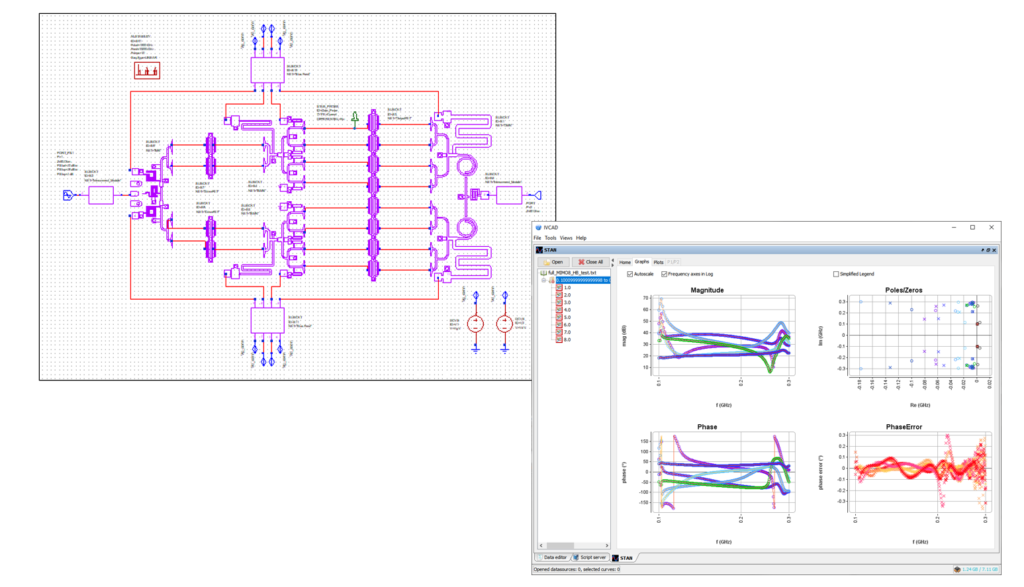
Designing a wideband power amplifier with high output power can be quite challenging. It requires a complex structure, and multi-stage amplifying cells must be used to achieve the desired specifications. The available stability analysis techniques cited above are not useful with such structures as it does not support multi-stage Power amplifiers where the stability issue can be located in the inner structure of the complex circuit.
What to expect from a Stability analysis Technique
To support challenging Power Amplifier designs, a stability analysis tool must be able to assess the stability for both linear and non-linear conditions. Indeed, even though large signal stability is not usually performed in the literature on PA design, it is a very important step that cannot be ignored. The stability analysis method should also provide more information about the circuit behaviour and allow parametric analysis using multi-node and Monte Carlo types to identify the oscillation’s nature and location.
Moreover, the complexity of the different stability analysis techniques has always been a limiting factor. Therefore, the desired method should be simple to use and intuitively identify the PA’s stability condition without any complex interpretation or ambiguity. It should also be compatible with different CAD simulators available commercially.
Poles and Zeros identification Method
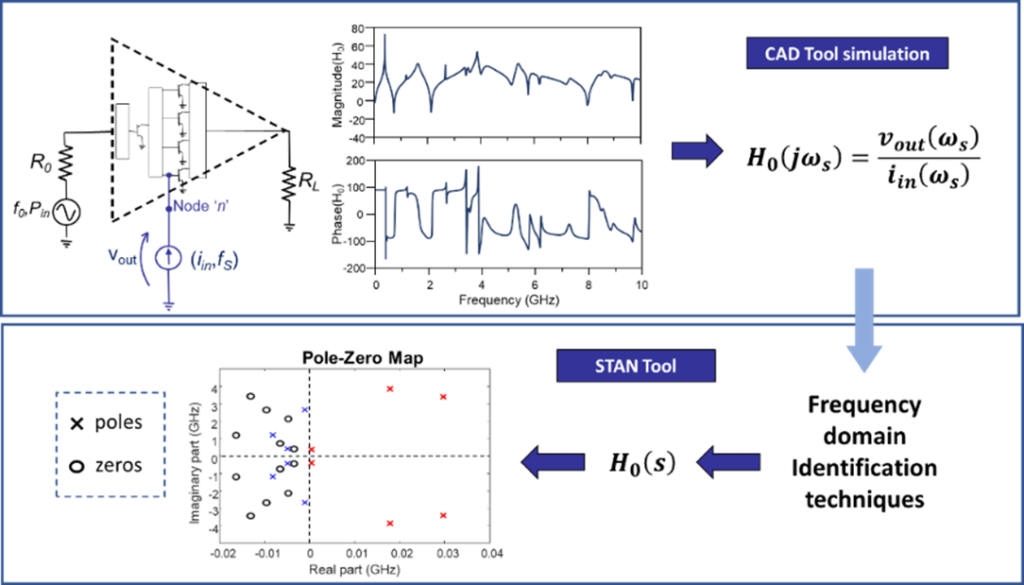
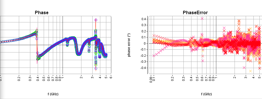
A pole-zero identification method is a powerful tool based on a rigorous and unique analysis in linear and non-linear conditions. Thanks to this technique, the designer obtains more insight into the circuit dynamics, giving information about the nature and location of the oscillation. The parametric and multi-node analysis enables efficient detection of instabilities in wideband MMIC power amplifiers.
When the other methods failed to detect the oscillation of a cascode amplifier structure, the pole-zero identification method could detect an oscillation at around a specific frequency. Moreover, using the multi-node analysis, the exact location of the oscillation was identified.
Large signal analysis is also possible with this technique, which permits establishing the exact conditions of input power and/or load impedance at which instability may arise.
Thanks to its capabilities, this method helps power amplifier designers identify and locate the instability in the circuit, decide on the stabilization technique and finally choose the best combination to achieve the expected specifications.

AN : Selecting the circuit’s node with STAN
AN : Rollet Factor versus Pole-Zero Identification
AN : How to Select the Frequency Range for Analysis ?
STAN and the STAN Wizard Installation and Use in AWR (NI)
MT930Q is a standalone module of IVCAD. Different templates from ADS or Cadence MWO are supplied with the module to run different simulations to extract the information necessary for the stability analysis.

