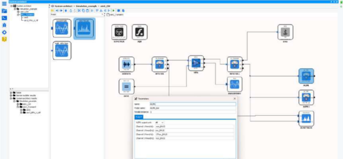
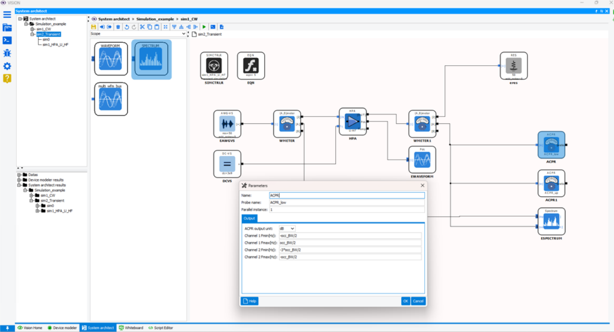
Once the various circuits used in the chain have been identified and modeled, they are represented by icons, which can be used directly in the schematic editor to reproduce the system architecture.
Different families of tools can be used to check the system performances
- Simulation control blocks: Configure simulation by selecting solver (algebraic/dataflow), domain (CW/envelope transient) and analysis type (nominal, sweep, statistical, noise) and set multithreading option.
- Nonlinear blocks: VISION behavioral models such as HPA and LNA.
- Linear distributed & lumped blocks: RLC and ground components, VISION SNP behavioral models and advanced function capabilities for Phased-Array Antenna analysis.
- Source blocks: Provide inputs for simulation by defining and generating signals (CW, 2-tone, pulse) or loading signals (custom IQ data or using Waveform Generator)
- Scope & Probes blocks: waveform & spectrum analyzers, performance analysis such as Instantaneous Power, Average Power, Power Added Efficiency (PAE), Adjacent Channel Power Ratio (ACPR), Noise Figure (NF)
- Transducer blocks: Mathematical function blocks and route signal blocks such as Bus.
- Multiblock and connector blocks: User-defined blocks designed from edited VISION diagram with customizable input and output ports.
- Co-simulation blocks: Custom block function block linked to MATLAB® script or user API dll, import function block of exported VISION macro-model with VIS100F module
To manage architectures of increasing size and complexity, an effective strategy is to organize the equivalent system diagram into several groups using components known as “multi-blocks”.
A multiblock is essentially a group of circuits within a diagram that encapsulates a subset. It is therefore possible to include several multi-blocks in a single diagram, or even to nest multi-blocks within one another. Therefore, an architecture with greater depth can be defined, with the following benefits:
- A hierarchical organization in the schematic editor can be based on a multi-layer structure for an easy navigation
- it simplifies diagram display by minimizing the number of blocks visible in the main window.
- Specific interfaces with specific inputs and outputs improve integration and interaction within the block diagram.
Once created, on multiblock can be added in the library of available models, and reused in different schematics across different project templates.
Waveform Generator & IQSTAR probe feature
Module VIS100E provides Waveform Generator tool for evaluating in simulation key performances of modern telecommunication systems such as EVM and BER figures of merit. The Waveform Generator interface allows to:
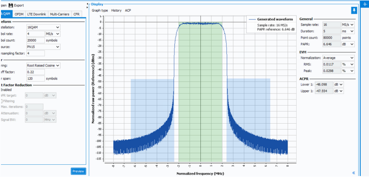
- build complex IQ waveforms without programming skills requirements (limited to PSK&QAM modulation in VISION 2.4);
- get a graphical preview by plotting the spectrum or CCDF;
- export as a iwf file format suitable for IQSTAR measurement setup and VISION simulation setup.
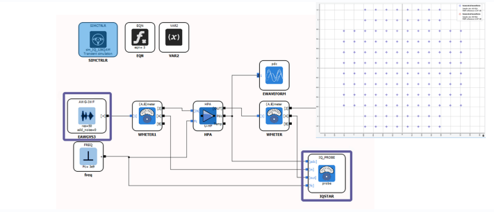
The diagram editor provides signal source block to import iwf file generated from Waveform Generator and IQSTAR probe for demodulation and analysis. Simulation results are formatted in such a way that they can be easily compared with IQ validation measurements made with IQSTAR software.
MATLAB® API feature
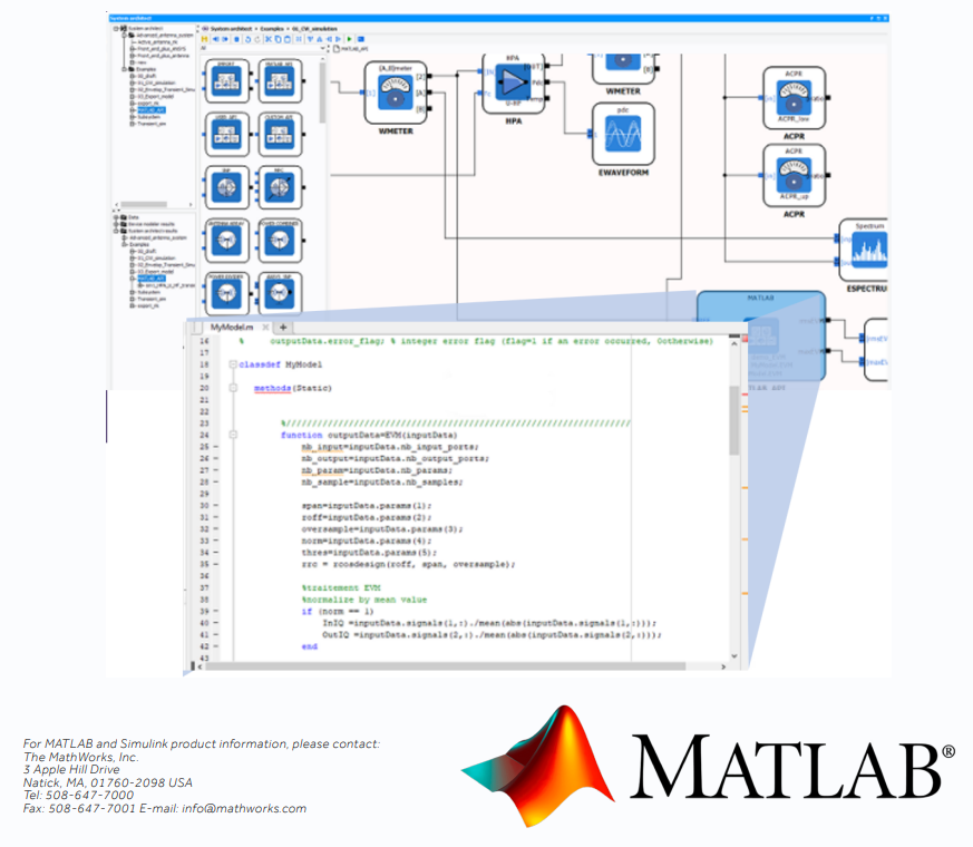
With the System Architect, algorithms designed in MATLAB® (a product of Mathworks) or C/C++ languages can be used during the simulation.
The USER & MATLAB® Application Programming Interfaces allow customizing models and/or signal processing algorithms by integrating user-defined C/C++ dlls.
Alternatively, user-defined MATLAB® scripts can be encapsulated within a MATLAB® block in the diagram editor. As a result, IP and source code previously developed to run in a specific simulation environment can be reused and leveraged through realistic circuit models, extracted from the VISION environment.
This combination unifies the design flow of RF analog engineers and digital programming engineers to anticipate the true system behavior, made of both digital and analog circuits.
Whitebord Editor Bundle
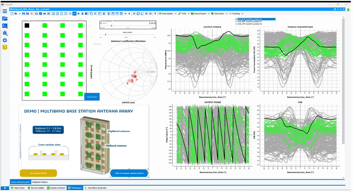
The Whiteboard tool allows the analysis of as much simulation data as possible without compromising flexibility. Circuit or system designers generally wish to import measurement or simulation data into a suitable environment to verify their design and/or the agreement between simulated results, measured performances, and reference data. If they don’t have dedicated tools, they use homemade ones, which are generally costly in development time, workforce, and maintenance.
This Whiteboard module allows creating and customizing as many graphics as necessary and positioning them into a user-defined template. It is possible to incorporate texts and images. An interactive display can be generated using different filters or sliders, including tables and graphics.
The data can be analyzed in a raw format or processed via an equation editor, allowing the analysis to be customized. The user can reload new measurements or simulation data in a predefined and customized analysis environment with a few clicks.
This tool is essential for the in-depth analysis of RF systems simulation results. The simulated quantities, the variables used, and the data size can be parameterized at any time.
Using the “Whiteboard Editor” (included in the VISION & Whiteboard bundle), the user can choose to analyze all the data on a single page or on multiple pages to create customized simulation reports.
Whitebord Editor / Scripting
Scripting module is a complementary and alternative solution used in the whiteboard (SCRPT module included in VIS100 System Architect module). This unlocks the complete control of the whiteboard project, from its page management to the data management including all the controls (Graph, Filter. Button etc…)
When a set of commands or functions needs to be executed several times, or saved for later use, this one can be developed and stored in a custom script.
In addition, built-in function libraries related to the simulation engine can be called up and tested in a complete program based on the Script Editor language, using the Integrated Development Environment (IDE).
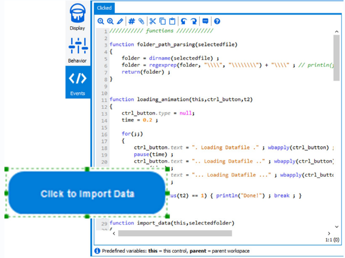
The (IDE) Script Editor offers powerful debugging functions to help the programmer developing its own data processing and methodology for a deep analysis of the results.