Large Signal Analysis & Waveform Engineering
AMCAD wideband comb generator has been developed for the characterization of nonlinear RF devices (transistors, amplifiers), enabling the measurements of absolute phase of the harmonic content of a signal and allowing Waveform engineering capabilities in time-domain Load-Pull.
Waveform engineering can be used to minimize the power consumption and to optimize the power added efficiency of amplifiers, operating in a switch-mode class of operation like Class F or inverse Class F. See IVCAD MT930GA Large Signal Analyzer operating manual
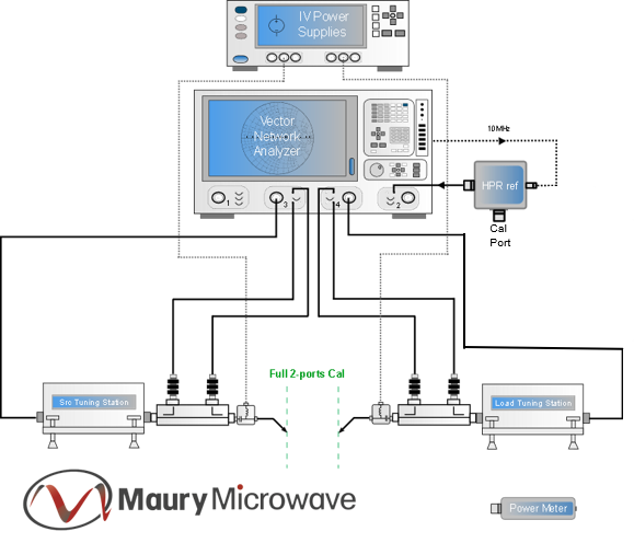
Used in combination with IVCAD Software, this Comb Generator enables accurate phase-calibrated measurement of harmonic signals when measured with a Vector Network Analyzer, in order to provide true RF waveform measurements at the DUT reference plane.
This phase calibration standard allows optimizing the operating class of RF transistors using harmonic load tuning with IVCAD MT930C VNA based load-pull measurement bench control and IVCAD MT930GA Time-Domain LSA software module.
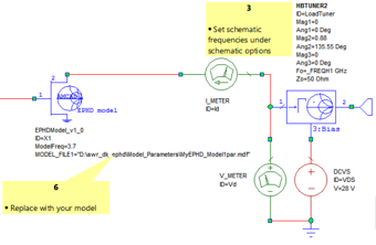
RF Transistor EPHD Behavioral Modeling
RF measurements of magnitude and phase-calibrated harmonic signal can be used to extract transistors’ Enhanced Poly-Harmonic Distortion (EPHD) Model using IVCAD MT930R1 IVCAD software module.
See IVCAD MT930R1 Behavioral Modeling Extraction and Simulation operating manual
With IVCAD MT930C VNA Based Load Pull and IVCAD MT930GA Large Signal analysis modules, harmonic phase-calibration and harmonic impedance control are used to generate time-domain load-pull data which can be used to extract a transistor model directly from large-signal measurements.
Using the comb generator, a transistor model can now be extracted within 2 or 3 days at several frequencies. Including, calibration, measurements, extraction, and model validation time.
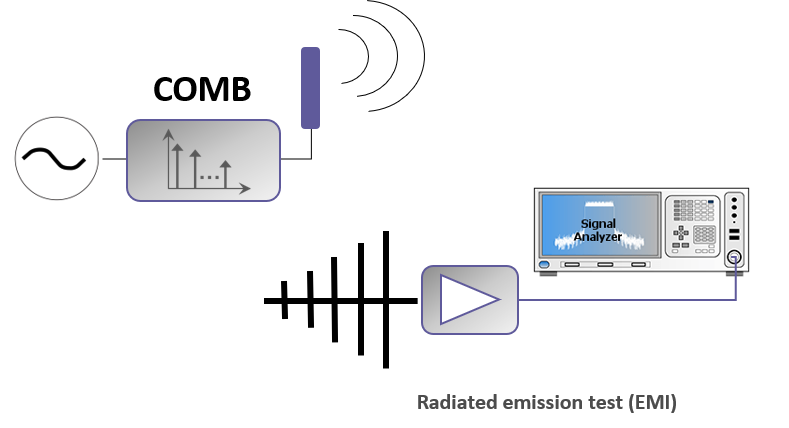
EMC testing
The HPR7227A comb generator can be used as a very broadband reliable EMC signal source reference for rapid and efficient testing.
The HPR can generate signals up to 26Ghz at frequency intervals as small as 10MHz.
EMC Laboratories calibrate their test sites, instrumentation and accessories regularly. Calibration procedures can be complex and time-consuming. However, in EMI/EMC test site validation, using calibrated instruments does not prevent bad readings. These may be due to multiple causes, such as damaged receivers, broken cables, bad connections, or a defective antenna.