The biggest challenge engineers face when designing power amplifiers for 5G or LTE applications is proving that their devices can handle the number and variety of waveforms, frequencies, and bandwidths allowed in these applications. It becomes critical to evaluate the amplifier’s impact on signal quality in as many scenarios as possible.
To limit the number of scenarios, you need access to waveforms that conform to established standards. As part of the standardization process, 3GPP has defined several types of reference waveforms (Test Models) that serve as the basis for tests ranging from throughput to EVM testing. The use of these test models in LTE or 5G NR networks is essential to ensure conformance, assess performance, benchmark, troubleshoot, validate new features and meet regulatory requirements. It contributes to the successful development, deployment and operation of LTE or 5G NR networks and devices.
The test models (LTE E-TM or 5G NR-TM) are set of signals defined by 3GPP to define conformance test for transmitter tests in downlink mode. These waveforms hold significance as they encompass various modulation types and diverse resource allocations, including spectrum occupancy considerations. These include transmit signal quality, output power dynamics, Error Vector Magnitude (EVM) for various modulation schemes, Base Station (BS) output power, Occupied bandwidth emissions, Adjacent channel leakage ratio (ACLR), etc.
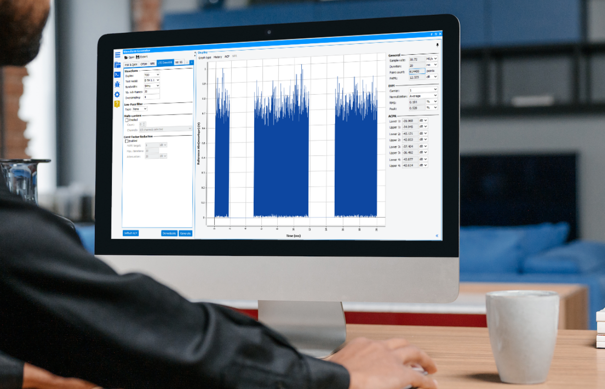
LTE Waveform Generator
As power amplifier designer, application engineers or characterization Engineers cannot be also network or system specialist, waveform generator tool allows users to easily create signals, offering flexibility to adjust settings according to LTE or 5G compliant E-TM, NR-TM waveforms. Users can export waveforms to an ASCII file, upload them to a signal generator to test devices or simulate them to our system simulator (VISION).
LTE Downlink tool allows to generate easily test models (E-TM) in FDD and TDD operating modes. Users can generate E-UTRA setting few parameters :

- Duplexing mode (FDD or TDD)
- FDD (Frequency Division Duplexing) : Each radio frame is 10 ms long and consists of 10 sub-frames. Each subframe contains two slots and is 1 ms long. Each slot is 0.5 ms long.
- TDD (Time Division Duplexing) : A TDD frame includes special subframes. A special subframe contains the downlink and uplink pilot timeslots (DwPTS and UpPTS) separated by a transmission gap guard period (GP). These three parts in a special subframe have variable lengths, but the total length is always 1 ms.
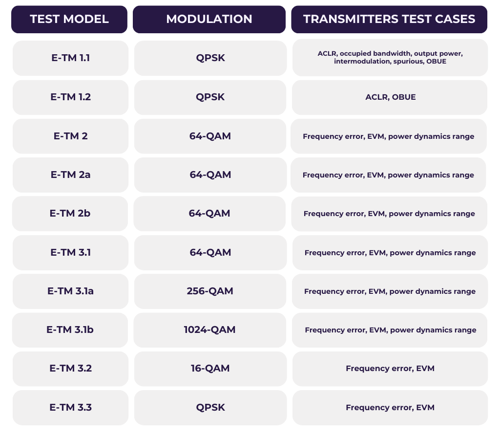
- Test Model name :
For testing of radio performance test cases, different E-TM models are used which have been already defined by 3GPP.
- Desired bandwidth: For each test models six signal bandwidth (BW) are available. Each signal bandwidth has an associated sampling rate and FF size and as shown in the following table.
- Number Subcarrier : Usually, test model (E-TM) are defined on 1 Frame totaling 10 sub-frames. To optimize IQ & DPD measurement speed, Decreasing the number of subframes in the signal, will decrease the waveform number of points.
- Oversampling : Defines the oversampling factor. The final waveform sampling rate will be equal to Symbol rate x Oversampling . Minimum value >0. In the case of the DPD application, the oversampling needs to be at least 4 times to ensure DPD efficiency on Adjacent Channel Power Bandwidths.
NR 5G Waveform Generator
IQSTAR 5G NR Downlink tool allows to generate easily test models (NR-TM) in FDD and TDD operating modes for FR1 or FR2 frequency bands and reach the standardization of transmission bandwidth and subcarrier spacing combinations. Users can generate NR-TM setting few parameters :
- Duplexing mode (FDD or TDD)
- FDD (Frequency Division Duplexing) (available only for FR1 frequencies). Each radio frame is 10 ms long and consists of 10 sub-frames.
- TDD (Time Division Duplexing) is a burst signal. Each radio frame is 20 ms long and consists of 20 sub-frames
- Frequency
- FR1 (410 MHz – 7.125GHz)
- FR2 (24.25 GHz – 52.6 GHz)
- Test Model name :
Different test models are characterized by different parameters such as number of RBs, type of modulation etc. Below is a list of the test models available depending on the frequency range
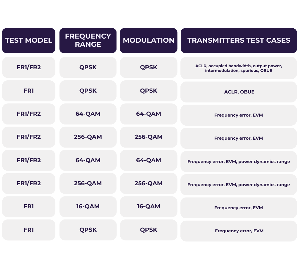
For testing of radio performance test cases, different TM models are used which have been already defined by 3GPP.
- Bandwidth (BW)
Depending on frequency bands (FR1 or FR2) several signal bandwidth (BW) are available from 5MHz to 400MHz.
LTE and NR 5G Demodulation
To evaluate transmit signal quality, EVM (Error Vector Magnitude) is the main metric used to quantify the accuracy of the modulation and demodulation processes. EVM measures the difference between the ideal or expected signal constellation points and the actual received constellation points. In practical terms, a lower EVM value indicates better performance, as it means that the received signal closely matches the expected signal. EVM is influenced by various factors, including noise, interference ,imperfections and non-linearity in the communication channel. To compute EVM standardized 3GPP demodulation process is mandatory. This complex process allows to retrieve the original baseband signal, which represents the original information that was modulated onto the carrier wave. IQSTAR LTE and 5G NR demodulation tool includes all the complex standardized demodulation steps as :
- Frequency and Time Synchronization:
- FFT (Fast Fourier Transform)
- Channel Estimation
- Equalization
- Demodulation of Subcarriers
- Cyclic Prefix Removal
- Combining Demodulated Subcarriers
- Decoding
Thanks to this rigorous process IQSTAR is able to provide detailed EVM measurement with representation including :
- Constellation diagram
- EVM versus sub-carriers
- EVM versus Symbols
- EVM versus resources block
- EVM versus Time
Multi-carrier Signal Generation and Demodulation
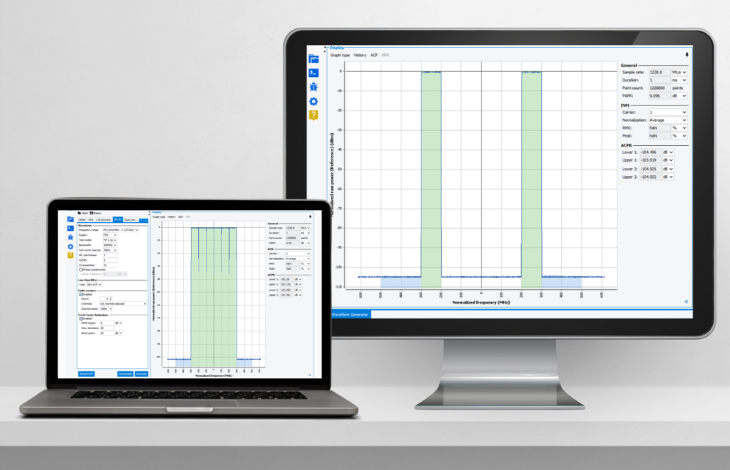
A multi-carrier signal is a type of signal in which data is transmitted simultaneously over multiple carrier frequencies. Instead of sending all the information over a single channel or carrier frequency, the data is divided into multiple substreams, and each substream is transmitted on a separate carrier frequency. This approach has several advantages, including improved spectral efficiency and robustness against frequency-selective fading and interference. For power amplifiers designers is the main way of testing the instantaneous bandwidth of their device. Nevertheless, generated and analyzed such as signals is one of the critical challenge faced by engineers in characterizing power amplifiers.
IQSTAR enables a simple multi-carrier generation allowing up to 10 consecutive carriers or dual large carriers spacing configurations. In top of waveform generation, IQSTAR allows calculation of Error Vector Magnitude independently for each carrier, offering precision in signal assessment and a robust tool for designing and testing RF systems. This progressive leap in signal characterization unfolds with IQSTAR, where multi-carrier signal capabilities redefine the landscape of power amplifier assessment.