INTRODUCTION
The evolution of wireless communications technologies has given rise to new architectures in the radio chain, from precoding to the active antenna, where different techniques have been developed to improve the capacity and coverage of the network.
Beamforming in Advanced Antenna Systems (AAS) including phased-array antennas or massive MIMO is designed depending on the number of final users and the characteristics of the deployment scenarios. Thus, radio transceivers must be tested in real conditions and different configurations to be efficiently implemented.
Circuit-level simulation of the radio chain is not straightforward when considering wideband complex modulated signals. Thus, system simulation becomes the better approach to analyze and test the antenna front-end, where the elements of the radio chain will be analyzed using behavioral models.
Between the main elements of the beamforming architecture there are the step attenuators and the phase shifters (Fig. 1), used to direct the antenna beam. DSA+DPS can be modeled as a Multi-Function Chip (MFC) where they will be characterized by a 2-port S parameters controlled by the attenuation and phase values to switch between states.
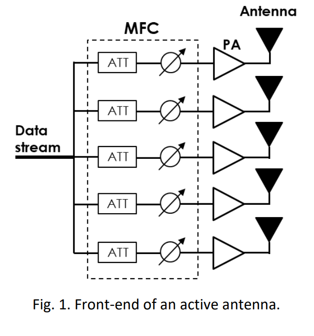
Between the main elements of the beamforming architecture there are the step attenuators and the phase shifters (Fig. 1), used to direct the antenna beam. DSA+DPS can be modeled as a Multi-Function Chip (MFC) where they will be characterized by a 2-port S parameters controlled by the attenuation and phase values to switch between states.
Extracting accurate behavioral models of this system can be cumbersome because of the high amount of measurement data and time necessary to get the information to model all possible states.
In this white paper, a new approach to model DSA and DSP systems will be presented using the MFC model extraction available in the VISION software considerably reducing the measurements time to extract an accurate model.
PROBLEMATIC
DSA and DPS are used in beamforming. This system introduces losses and phase shift to the radio chain and characterizing its real performances for all the control settings is not straightforward because of the high amount of data necessary to model all the possible states. Therefore, extracting a reliable model of the DSA+DPS system is time consuming.
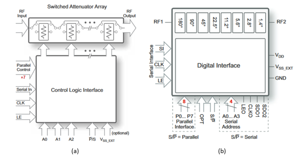
In this paper, the DSA XM-A3K8-0604D and the DPS XM-A3W1-0604D from Xmicrowave, that use the devices PE43712 (Fig. 2(a)) and PE44820 (Fig. 2(b)) respectively, will be used to illustrate the MFC model extraction and simulation using VISION.
The DSA and the DPS are controlled by 7 and 8 bits respectively, i.e., they can provide 128 and 256 possible states whose value will change with frequency. Thus, when connecting the two of them in series, the DSA+DPS system will present 32768 states/frequency.
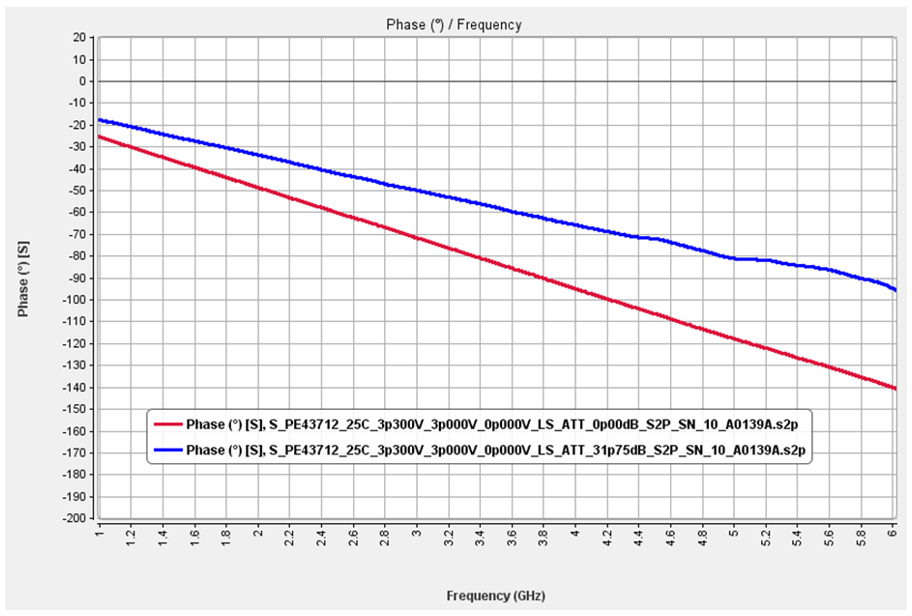
The DSA is introduced in the radio chain to modify the amplitude of the signal. However, under the presence of this component, the phase of the signal will also be varied. Fig. 3 shows the phase variation of the DSA in the frequency band 1 GHz – 6 GHz for the first state (red, attenuation = 0 dB) and the last state (blue, attenuation = 31.75 dB). As can be observed in the figure, there will be a variation in the phase up to – 140° for an attenuation = 0 dB and -90° for an attenuation = 31.75 dB at high frequency.
Moreover, the DPS, as in the case of the DSA, will not only modify the phase of the input signal but also its amplitude. Therefore, both the DSA and the DPS will modify the amplitude and phase of the input signal and this behavior must be taken into account in simulation to accurately predict the real behavior of the system.
Additionally, even if manufacturers may provide the S parameters information for each state, handling all files in simulation to predict the real performances of the DSA+DPS system is not straightforward without a behavioral model. Thus, the solution will be to measure a reduce number of states allowing the extraction of an MFC model that will be accurate in terms of configuration states when using the appropriate interpolation algorithms. Such a knowledge of the exact phase shift and power attenuation, for any digital control will enable a better calibration of the system at the computer aided design stage level. Indeed, if known, every unwanted phase or power variation can be then anticipated for any control settings.