
iTest BILT Setup Instruction & Driver Details
Model Supported :μBilt (BN103), tinyBILT (BN105), BN110, BN120.
- DC
- Pulsed
System Overview
- Mainframe
- Front Panel
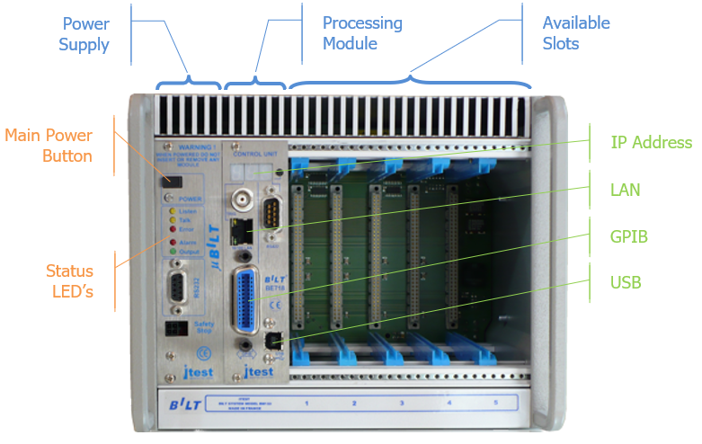
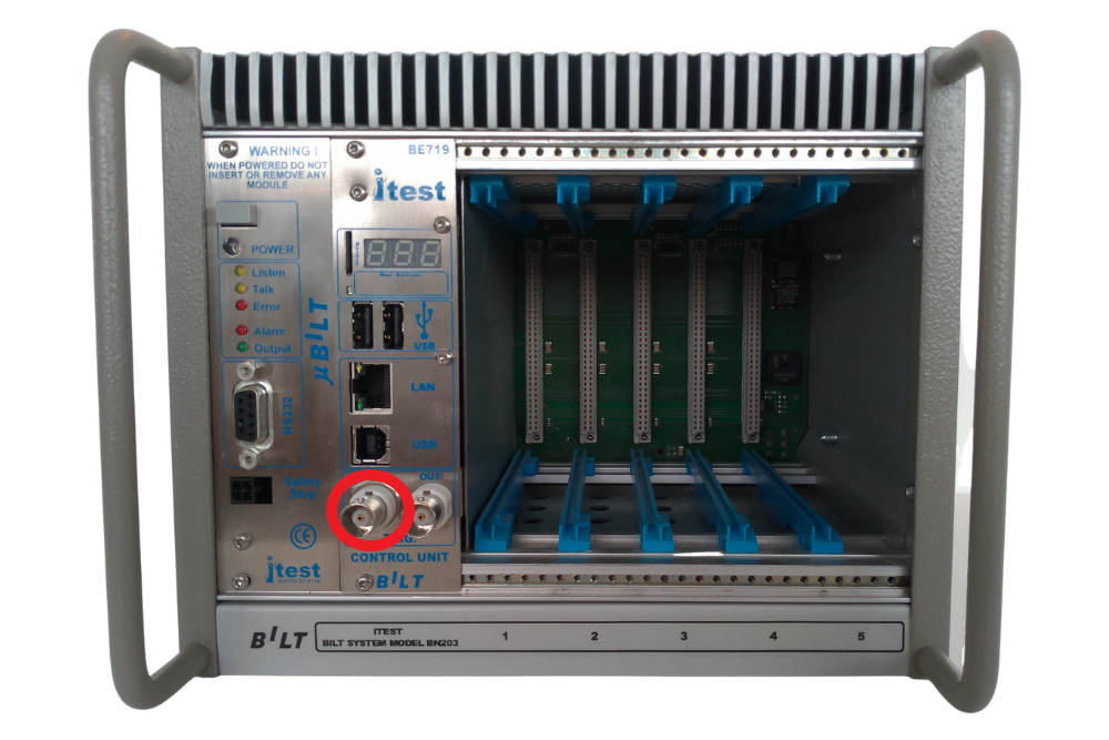
The BILT mainframe (BN103) is equipped with a power Supply unit (BE103), a processing unit (BE718) and five available slots that allow the user to add several I-V modules.
The power Supply unit (BE103) allows the user to power up and down the mainframe with the main power button, and to check the status of the whole system through the status LED’s.
The processing unit (BE718) drives the whole system and allows the user to communicate with the instrument trough several ways: 1x LAN connector, 1x GPIB connector and 1x USB connector are provided. The 3-segmented LED’s screen displays the IP address of the instrument in a sequence of four numbers; default address is in the 192.168.150.0/24 range.
- Rear Panel
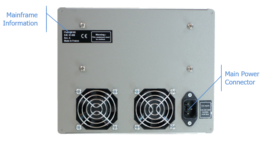
On the rear face, you will find the mainframe information label (P/N, S/N, Revision, Qualification ... etc.), 2x fans to extract the air, and the main power connector (110/220VAC).
- Front Panel
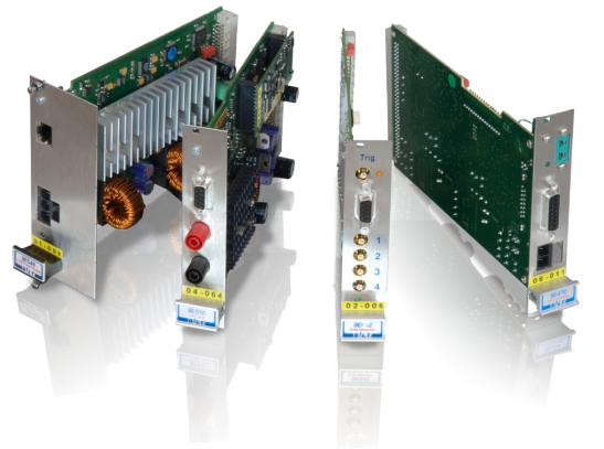
Supported Cards
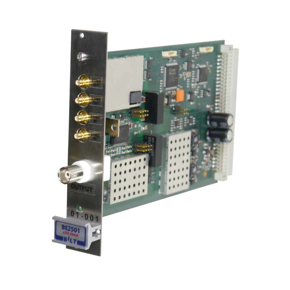
- BE2501
- DC / Pulsed
- ± 25V / ± 200mA
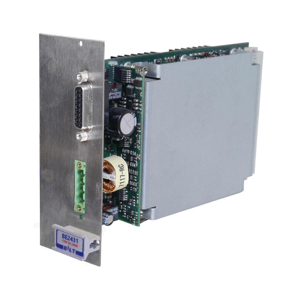
- BE2431 / BE2432 / BE2435
- DC
- +120V 5A
- BE8601
- USB Controller used to drive the BA2531 module.
- BA2531
- BE84x
- DC
- ± 15V / 200mA/2mA or 100µA and 10mA
- 6 Channels
- Can be used as :
- Same output on every channel
- Independent control of each channel
- Digital IO with selectable number of channels
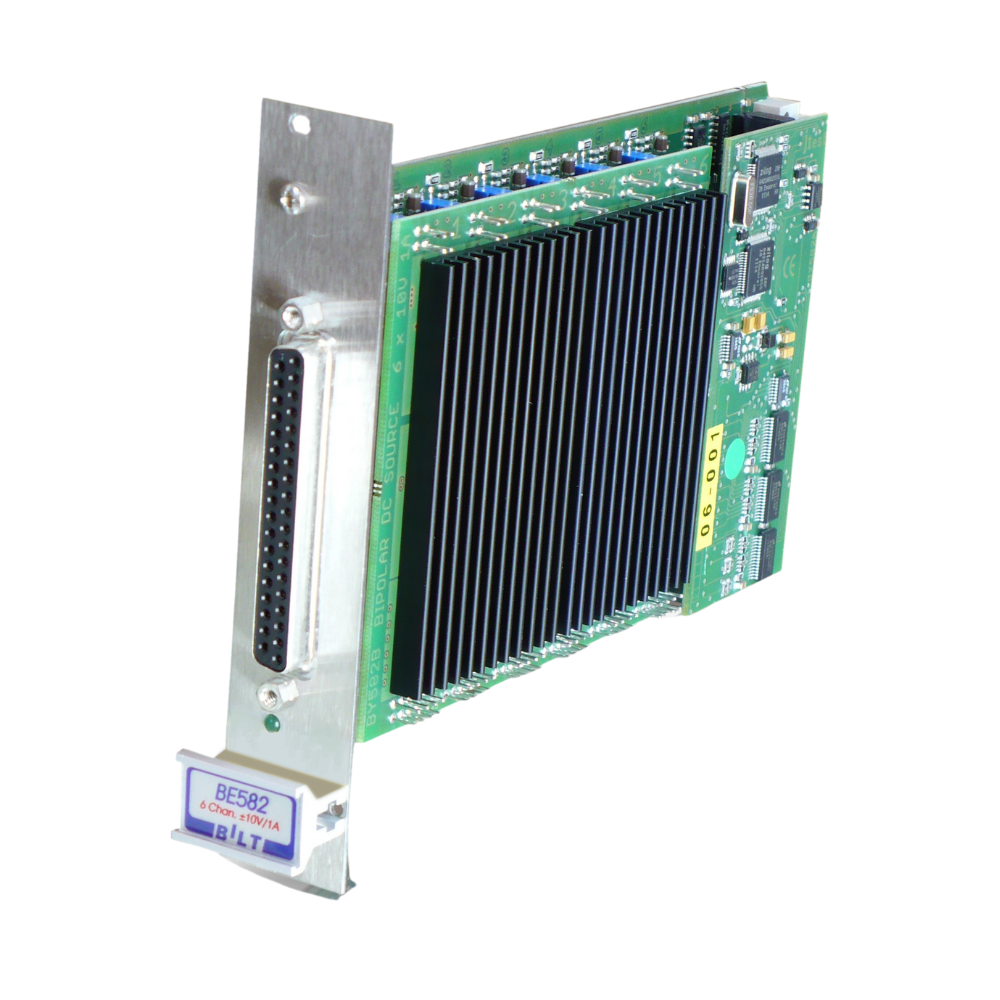
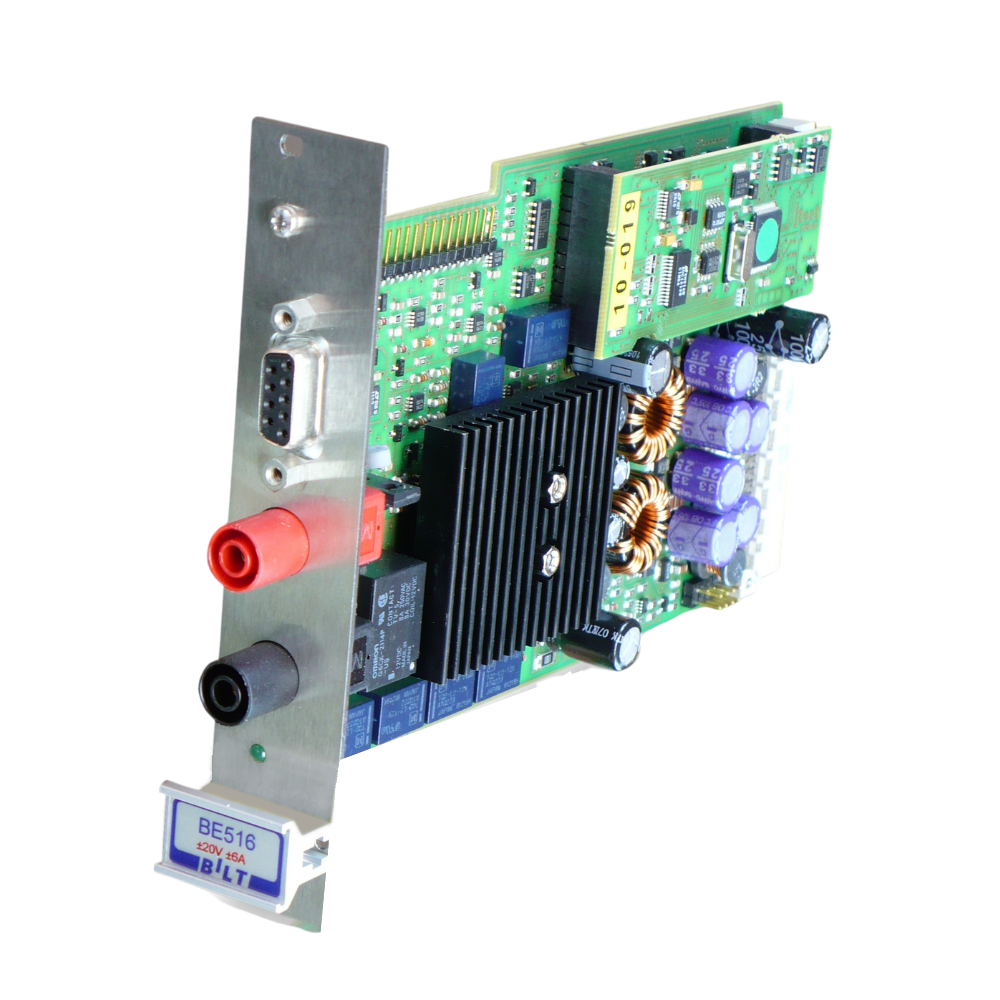
- BE516
- DC
- ± 20V / ± 6A
- BE510
- DC
- ± 20V / ± 4A
- BE427
- Temperature measurement
- 6 thermocouple Channels
- BE475
- Temperature measurement
- 1 thermocouple Channel

Operation
- PTrig and STrig
PTrig is the base time signal used to synchronize pulse generation, measurement and transient mask timings. The modules delays programming permits to define the different timings from this signal.
STrig is the sequence signal used to synchronize start, stop and emergency stop timings. Meaning, you can define delays between different power supplies for a start and a stop sequence, and even for emergency stops. STrig is active on low level (e.g. connected to Ground) and inputs usually have a pull-up; meaning unconnected input keep STrig inactive and so the output module powered OFF.
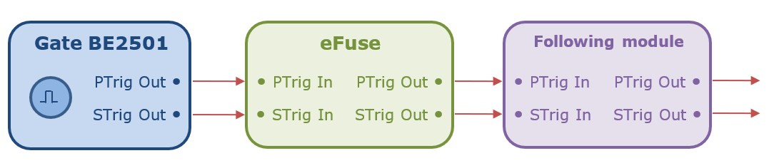
PTrig and STrig are chained signals, meaning that the PTrig and STrig outputs from the gate module goes to the PTrig and STrig inputs of the eFuse, the PTrig and STrig outputs of the eFuse to any other module used (RF Source, another eFuse, … etc.), … etc.
The gate module is the one that generates original PTrig and STrig signals. Thus, if you do not use any gate module, you can use an AWG (Arbitrary Waveform Generator) to generate the PTrig signal, and connect STrig to ground to force its state to ON.
- Trigger In BNC ConnectorBilt system can trigger every slot with only one BNC cable. To do so, connect the trigger signal to the Trigger IN BNC connector and specify it in the driver advanced options.
- Timeline
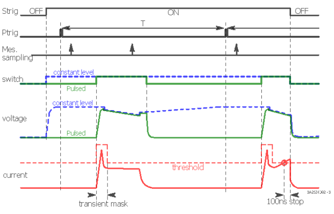
STrig must be ON to allow any power output.
In pulse mode, once a PTrig signal is received,
- a pulse signal is generated on the output according to the delay and width given by the user.
- bias and in-pulse measurements are done according to the delays given for each of them.
In DC mode,
- DC signal is generated on the output.
- bias measurement is done.
If a current threshold is reached during transient or current-established level, an alarm is transmitted to the system to power it down.
If STrig becomes OFF during operation, the power down sequence is initiated.
Setup
- General case
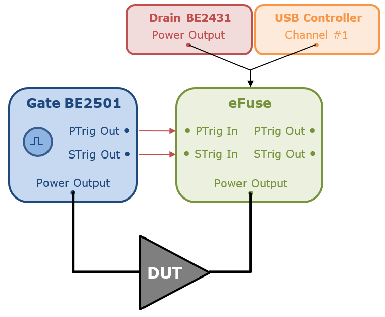
The full system described in this setup allows the generation and the measurement of the DUT in DC or Pulsed mode with eFuse protection on the drain.
- Pulsed mode with External Pulse Generator
If an external pulse generator is used, then connect the trigger signal to the Trigger IN BNC Connector. In IQSTAR Setup, every card will be set to "External" Trigger and theUse Trigger In BNC connector over PTrig In option need to be set to true for each card used.
- Pulsed mode with Internal Pulse Generator
If an internal pulse generator is used, then the master trigger will be one of the BILT Card. In IQSTAR Setup, the master trigger card will be set to "Internal" Trigger with the Use Trigger In BNC connector over PTrig In option need to be set to false. Others card will be set to "External" Trigger and the Use Trigger In BNC connector over PTrig In option need to be set to true for every cards.
The PTrig Out connector of the Master Trigger Card need to be connected to the Trigger IN BNC Connector.
IQSTAR Setup
The definition of the BILT configuration is defined in IQSTAR using Power Supplies schematic:
- Power Supplies setup
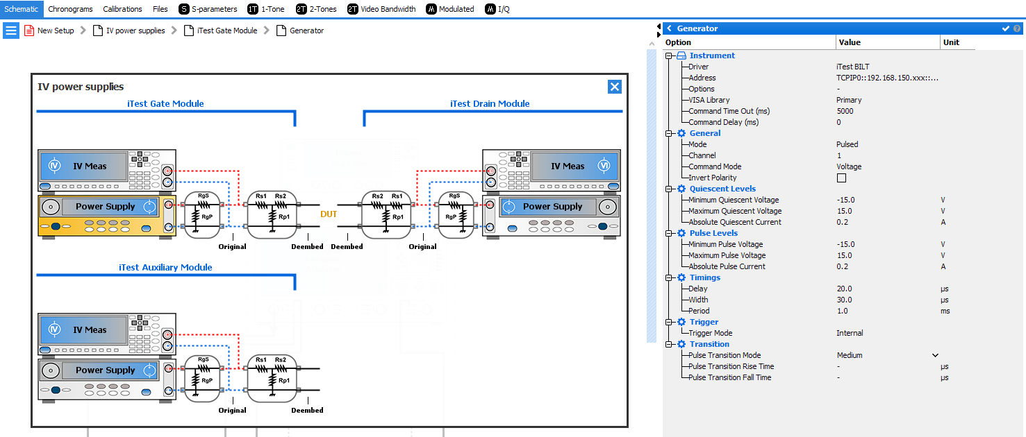
- Driver: iTest BILT
- Address: address of the BILT to communicate with it
- with LAN, the VISA address is something like TCPIP0::192.168.10.140::5025::SOCKET (IP Address appears on the BILT segmented-LEDs display)
- with USB, the magnifier icon scan all the instruments and help to find the USB VISA address to specify
- VISA library: Default. Select the VISA layer to use
- Command timeout: 5000. Define the time to wait before expecting the command failed to achieve
- Command delay: 0
- Mode: DC or PulsedNote: BE2431 / BE2432 / BE2435 probes need an eFuse to be able to generate a pulsed signal
- Channel: the slot used by the module in the BILT mainframe
- Command Mode: Voltage. Define if the generation is done as a voltage source (direct normal behavior), or as a current source with a loop back on the voltage to drive it likewise.
- Quiescent voltage limit: Define user settable quiescent voltage limits
- Quiescent abs current limit: Define module max current limit output
- Pulse voltage limit: Define user settable pulse voltage limits
- Pulse abs current limit: Define module max current limit output when pulsed
- Pulse delay: Define generated pulse delay
- Pulse width: Define generated pulse width
- Pulse period: Define generated pulse period
- Trigger: Define the source of the trigger.Note: If modules are chained for Pulse, use ‘Internal’ trigger generator, while the other ones use ‘External’ trigger.
- Transition: Not used by this driver
- iTest BILT Driver option : Power Supplies Options
To set the specific driver options, click on
 icon in options from instrument section.iTest BILT Driver Power Supplies Options are the following:
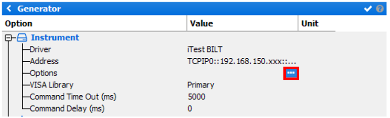
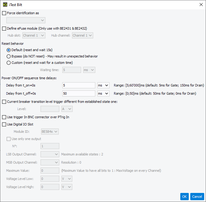
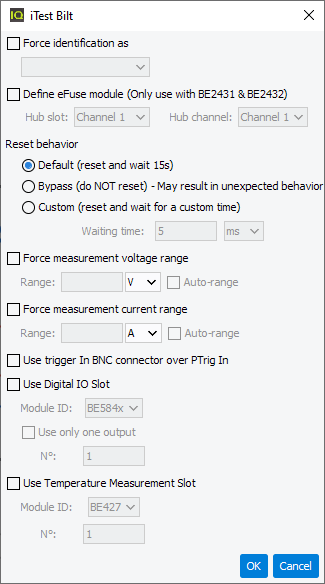
- Force Identification As: Used if the mainframe is not detected correctly to force the models (should not be needed to use)
- Define eFuse Model (Only use with BE2431 and BE 2432):
- If the channel is a not a BE2431 / BE2432 / BE2435, no eFuse can be connected on it and thus must be unchecked
- If the channel is a BE2431 or a BE2432, a BA2531 channel can be
defined
- Hub slot: mainframe slot of the USB hub used for the eFuse
- Hub channel: USB slot to which the eFuse is connected on the USB hub
- Reset behavior: Default or Bypass or Custom. The reset of the BILT
takes quite some time and does not reset all parameters. The timing of the
reset depends on each system and on the connected probes and eFuse on it.
The end of the reset cannot be checked by software, thus a hard timing must
be specified.
- Default: perform a reset and wait 15s to perform it
- Bypass: does not perform a reset
- Custom: perform a reset and wait for the user specified Waiting time
- Power ON/OFF Sequence time delay: Define the timing to wait before powering up and after powering down the system. This replace the Wait between IV power supplies switch … and Power ON sequence of the main setup editor dialogbox.
- Current breaker transition level: Define a current breaker level
different during edge transitions. Current breaker is only available with
the eFuse.Note: Current breaker specifications for BILT are: range 1A/33A ; accuracy 200mA + 0.5%
- Use Trigger In BNC connector over PTrig In: If checked, the trigger signal must be connected to the Trig In BNC connector in order for the Bilt to be triggered. The main advantage of using this connector over some module's PTrig In is related to the input impedance. The Trigger In BNC is a high impedance input whereas the PTrig In is a 50 Ohms input. If the triggering device has a 50 Ohms output, the signal voltage will be devided by two with a 50 ohms input on the triggered device. This can lead to bad or inexistant triggering and so bad measurement or timeouts.
- Use Digital IO Slot:
- Module ID: ID of the card to use with Digital IO.
- Use only one output: Select only one output of the selected
Module.
- N°: Output Channel
- LSB / MSB output Channel: Select the LSB / MSB to create the binary message.
- Maximum Value: Define the maximum value while all bits are 1.
- Voltage Level Low; Voltage output while bit is 0.
- Voltage Level High: Voltage outpute while bit is 1.
- IV measurement setup
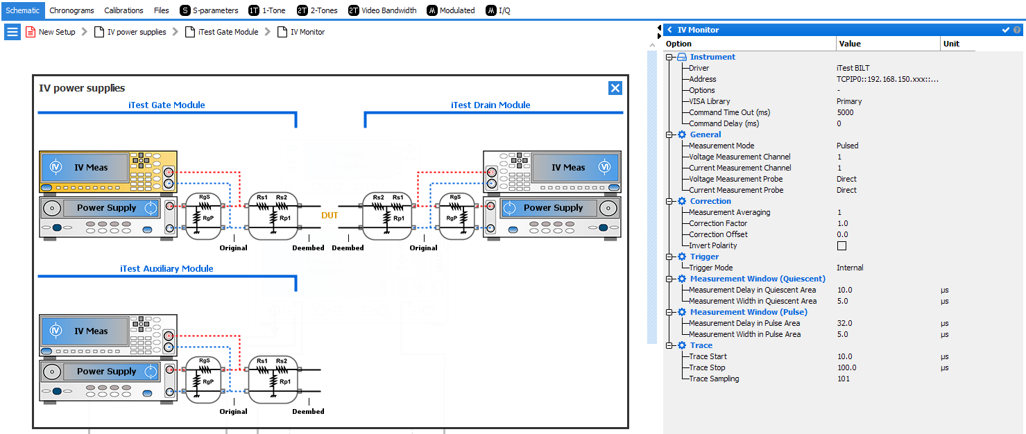
- Driver: iTest BILT
- Address: address of the BILT to communicate with it
- with LAN, the VISA address is something like TCPIP0::192.168.10.140::5025::SOCKET (IP Address appears on the BILT segmented-LEDs display)
- with USB, the magnifier icon scan all the instruments and help to find the USB VISA address to specify
- VISA library: Default. Select the VISA layer to use
- Command timeout: 5000. Define the time to wait before expecting the command failed to achieve
- Command delay: 0
- Mode: DC or PulsedNote: BE2431 / BE2432 / BE2435 probes need an eFuse to be able to generate a pulsed signal
- Voltage Channel: the slot used by the module in the BILT mainframe
- Current Channel: the slot used by the module in the BILT
mainframeNote: iTest BILT always work in Direct Mode.
- Averaging: Define the number of measurement to average
- Correction factor: Define the multiplicator coefficient to correct the measurement
- Correction offset: Define the additive coefficient to correct the measurement
- Trigger: Define the source of the trigger.Note: If modules are chained for Pulse, use ‘Internal’ trigger generator, while the other ones use ‘External’
- Trace definition: Not used by this driver
- Trace points: Not used by this driver
- Measurement window: Not used by this driver
- Measurement delay: Define the measurement position
- Measurement width: Not used by this driver.Note: The measurement integration times are defined by hardware but not specified by the manufacturer.
- iTest BILT Driver option : IV Measurement Options
To set the specific driver options, click on
icon in options from instrument section.iTest BILT Driver IV Measurement Options are the following:
- Force Identification As: Used if the mainframe is not detected correctly to force the models (should not be needed to use)
- Define eFuse Model (Only use with BE2431 and BE 2432):
- If the channel is a not a BE2431 / BE2432 / BE2435, no eFuse can be connected on it and thus must be unchecked
- If the channel is a BE2431 or a BE2432, a BA2531 channel can be
defined
- Hub slot: mainframe slot of the USB hub used for the eFuse
- Hub channel: USB slot to which the eFuse is connected on the USB hub
- Reset behavior: Default or Bypass or Custom. The reset of the
BILT takes quite some time and does not reset all parameters. The timing
of the reset depends on each system and on the connected probes and
eFuse on it. The end the reset cannot be checked by software, thus a
hard timing must be specified.
- Default: perform a reset and wait 15s to perform it
- Bypass: does not perform a reset
- Custom: perform a reset and wait for the user specified Waiting time
- Force measurement Voltage range: Force the use of a defined voltage range (to avoid measurement jumps for example).
- Force measurement Current range: Force the use of a defined current range (to avoid measurement jumps for example)
- Use Trigger In BNC connector over PTrig In: If checked, the trigger signal must be connected to the Trig In BNC connector in order for the Bilt to be triggered. The main advantage of using this connector over some module's PTrig In is related to the input impedance. The Trigger In BNC is a high impedance input whereas the PTrig In is a 50 Ohms input. If the triggering device has a 50 Ohms output, the signal voltage will be devided by two with a 50 ohms input on the triggered device. This can lead to bad or inexistant triggering and so bad measurement or timeouts.
- Use Digital IO Slot:
- Module ID: ID of the card to use with Digital IO.
- Use only one output: Select only one output of the
selected Module.
- N°: Measurement Channel
- Use Temperature Measurement Slot:
- Module ID: ID of the card to use with Temperature measurement.
- N°: Measurement Channel