Nested sweep
How to perform a simulation with nested sweep of variables. Here we present an example of a CW simulation in which the power of the input signal and the carrier frequency are varied.
To begin this task, you will need:
- A licence of VISION System Architect. See Installation and licence setup.
- Have done the task "Perform a CW simulation". See Perform CW simulation.
-
In the Applications window, click on Simulations_example1 >
Sim1_CW and drag and drop the VAR block from the
palette window in Simulation controls section to the
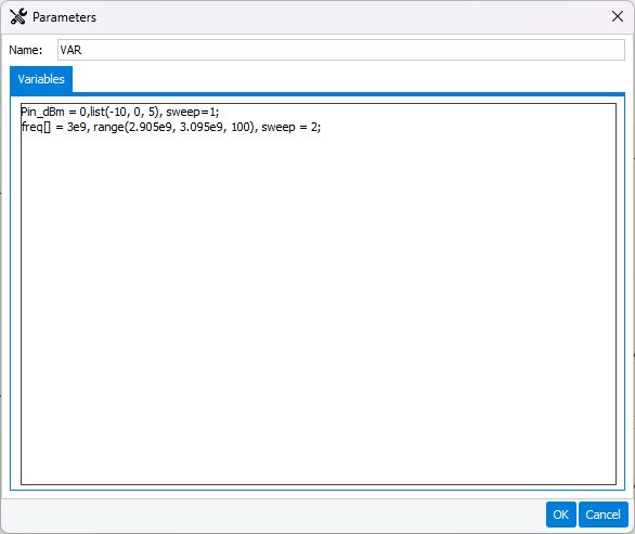
schematic window. Double-click on the VAR block to open the
Parameters window. We will set up two nested loops: the first one
varies the power of the input signal "Pin_dBm" (sweep = 1) and the second the
carrier frequency "freq" (sweep = 2). The syntax is as follows:
-
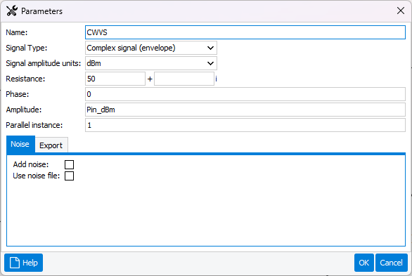
Double-click on the CW-VS block to open the Parameters window and
write "Pin_dBm" in the Amplitude parameter.
-
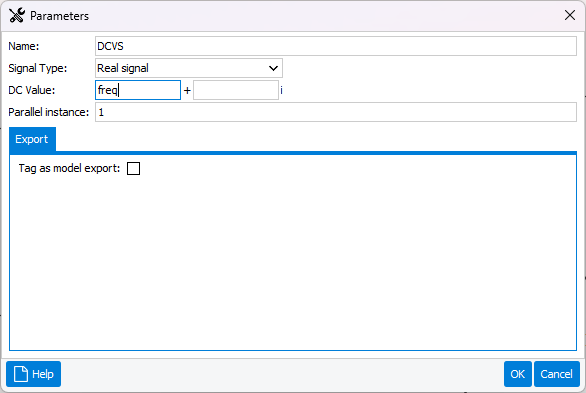
Double-click on the DC-VS block to open the Parameters window and
write "freq" in the DC value parameter.
-
Double-click on the SIMCTRLR block to open the Parameters window,
change the simulation name to "sim0_HPA_UHF_nested_sweep" and choose Sweep
analysis - nested sweep as Analysis type.
Figure: Sweep analysis - nested sweep 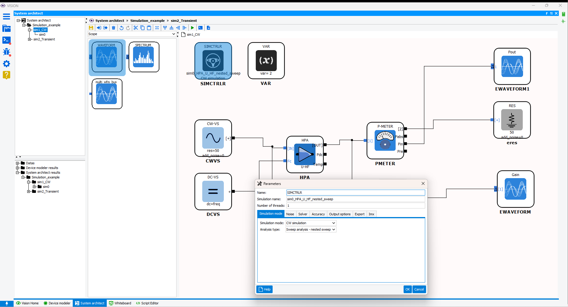
-
The model can now be simulated. In the menu bar of the workspace window, click
on Simulate>Run simulation or on the shortcut
 . The output console is displayed:
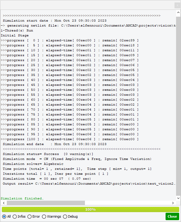
The console window contains the simulation time, the simulation mode, the repertory of the results, and also any warnings and errors encountered during the simulation. -
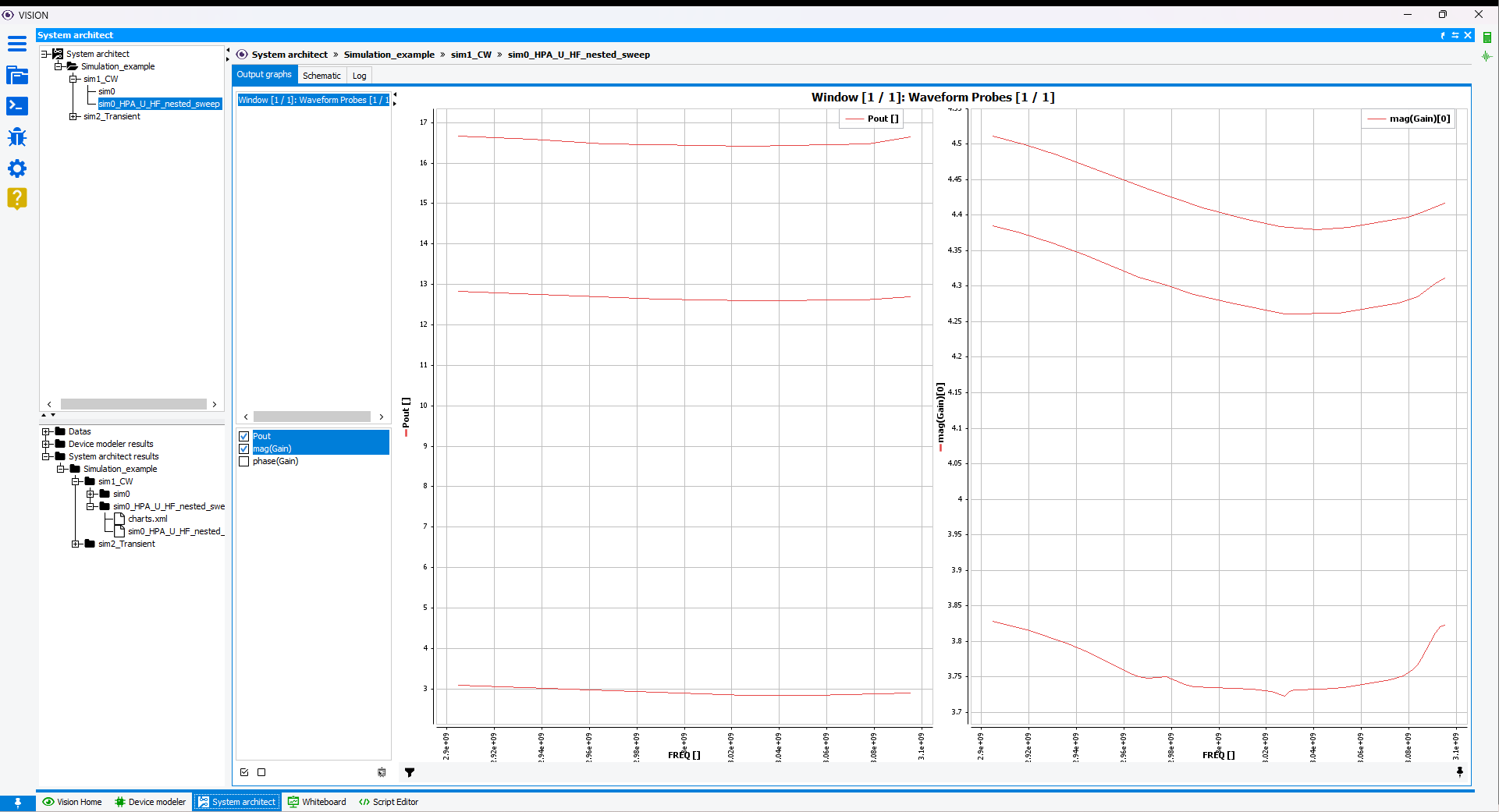
When closing the console window, simulation results appear in the application
tree in the folder named after the simulation "sim0_HPA_U_HF_nested_sweep". In
Workspace window, the Log shows console information. Click on
Output graphs tab to access the measurements provided by the probes.
Note that the curves are displayed according to variable that occurs in the last
loop. Here, the x-axis variable is the carrier frequency "freq".
Figure: Output graphs