Getting Started : "Pulsed measurements using AMCAD RF Switch"
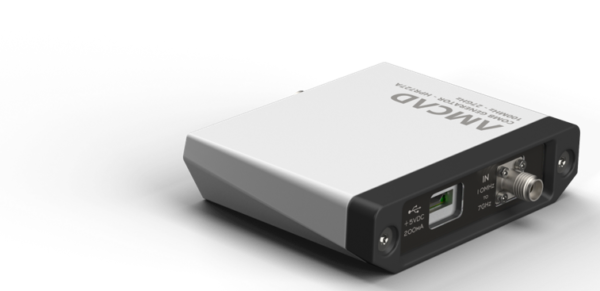
In order to perform some specific measurements, for example performing pulsed measurements with pulsed RF on a DUT but with only a CW RF Source, one solution consists of using a pulse modulator. AMCAD proposes using the SW1401A DC-11GHz switch (Link to product).
Setup and calibration
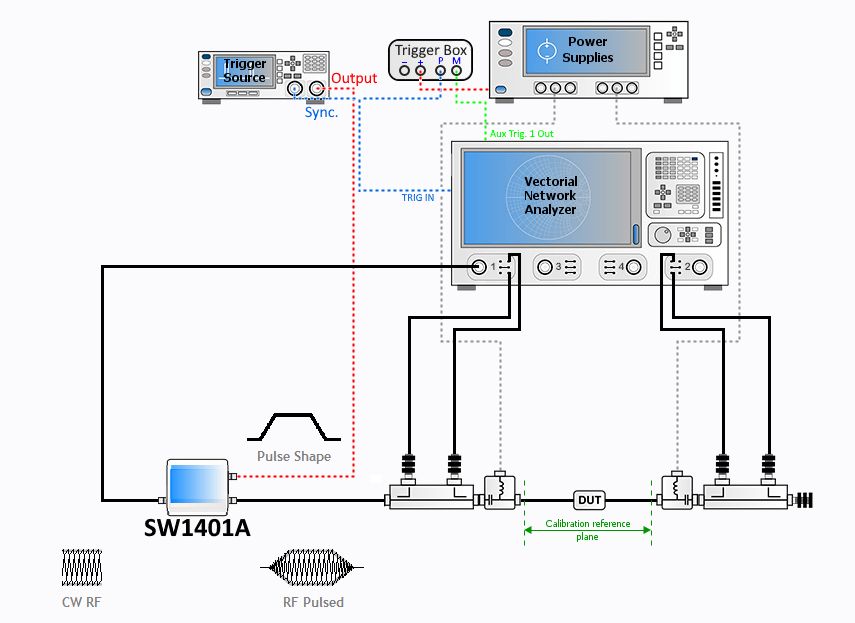
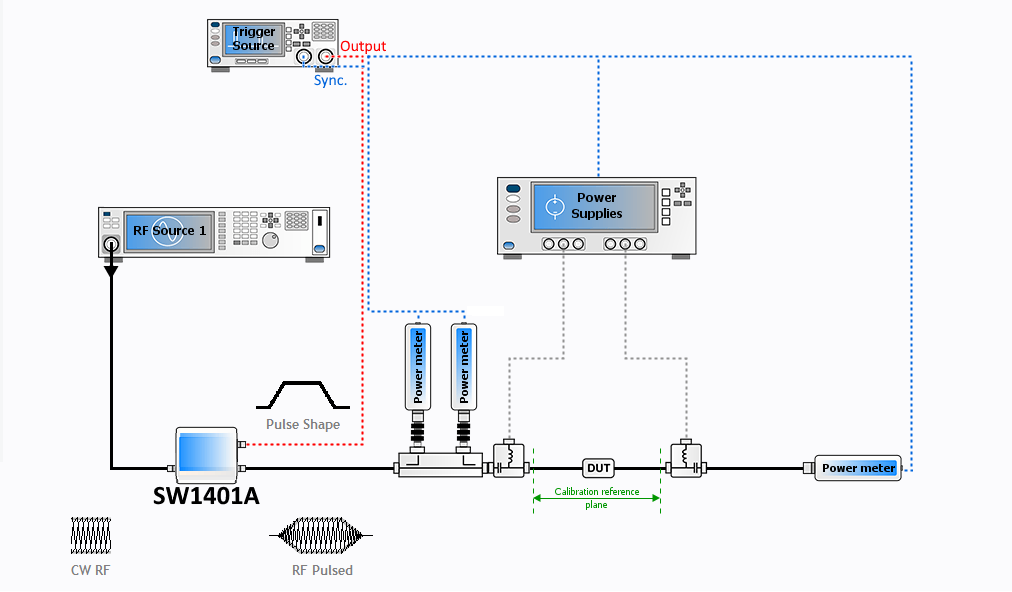
As described in Getting Started : "Overview on the Pulsed Measurement Techniques", cost sensitive application can lead to the use of this setup.In IQSTAR, a scalar setup will look like:
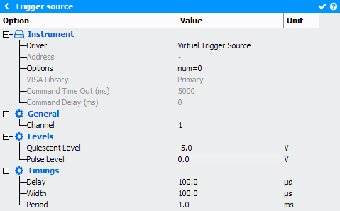
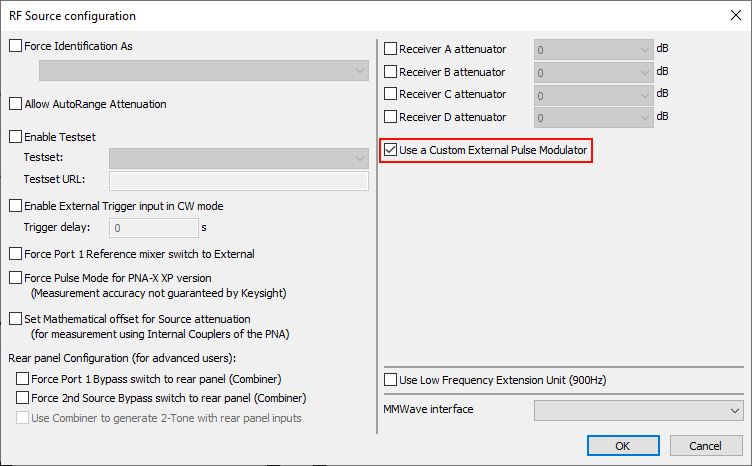
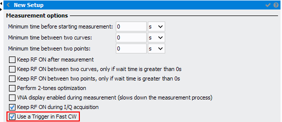
The VNA should be set working in Pulsed mode with this option checked. The specified timings will be ignored and only asynchronous CW or synchronous WBF will be available. To learn more about those measurements and have a full parameters description, please see the IQSTAR Pulsed-RF Measurement with a Basic VNA.
Before starting a new calibration, make sure a power meter is configured in the setup in case of a VNA based setup (vectorial). The power meter should be configured in CW in order to calibrate.
When performing a calibration, there is multiple configurations to take into account. We will take as an example the case where we do have a modulator on the input path.
- Vectorial calibration (Full 2 Port / 1 Port Enhanced): These
calibrations are using the VNA sources and receivers in CW. As they are set
in CW, we need to perform those calibrations type as in the setup, so with
the modulator in the RF path.
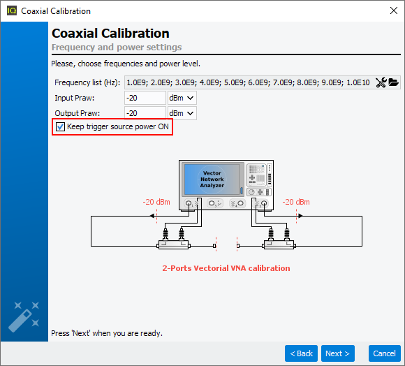
An option is available to set the state of the trigger source during the calibration. In this case, it is mandatory to check it as the switch is used. It can be unchecked if the trigger source is declared in the setup, but not used to control a switch as in this case.
- Scalar calibration (Absolute Power / Amplitude Calibration): When
performing those types of calibration, the option to keep the trigger source
ON is not available as the goal is to know the power offset (which is done
correctly in CW):
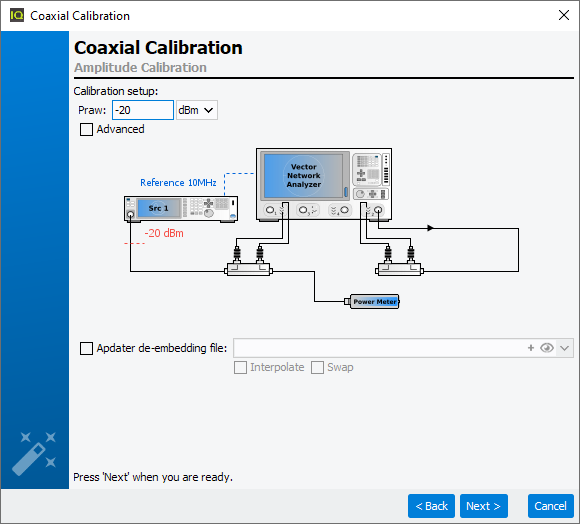
If declared, the source is not the VNA anymore but the external RF Source.
For more information about the calibrations, please refer to 2. Calibrate a Setup.
Measurement
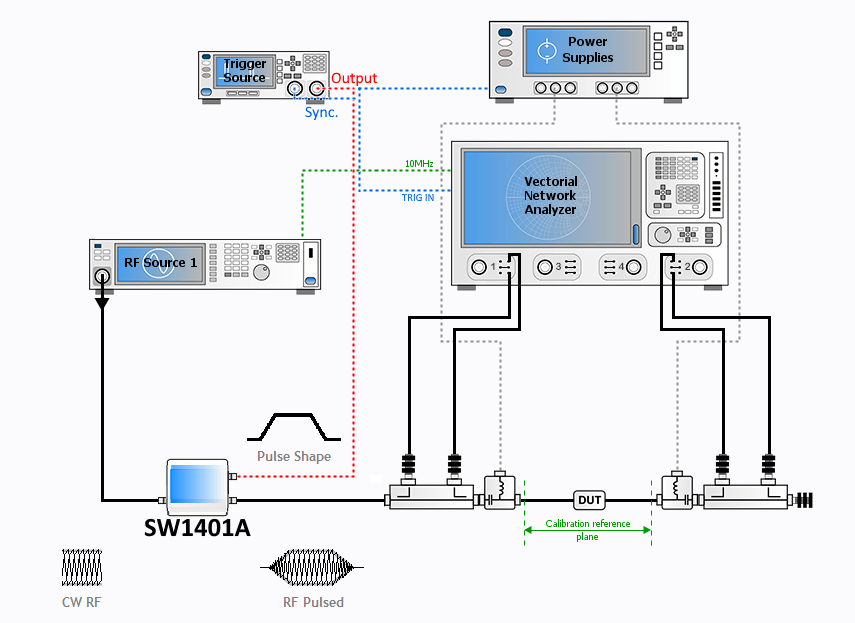
For the Fast CW mode available in 1-Tone and 2-Tones, the hardware configuration is different from the simple pulsed measurements with an external modulator. This measurement is only available with a Keysight VNA.
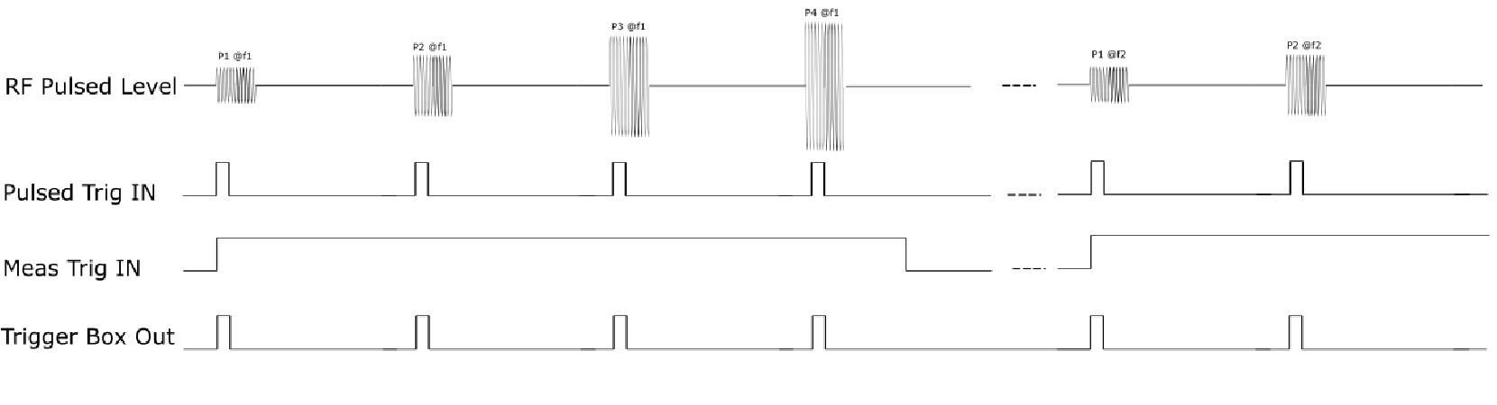
In this case, the schematic looks like: