Getting Started : "AMD Xilinx ZCU670 including Wupatec firmware"
Features
- 10MHz-7.125GHz Vector Signal Transceiver (VST) based on AMD RFSoC DFE ZCU670 evaluation kit
- Dedicated “Wupatec” firmware to run the VST like a benchtop instrument grade solution
- Measurement of RF Power Amplifier in base station-like conditions
- LTE/5G NR PA Tests with signal generation and analysis bandwidth up to 1.95 GHz
- 1-tone measurements: CW and pulsed CW characterization with configurable rise/fall time
- 2-tone generation for video bandwidth analysis (Additional Spectrum mandatory)
- IQ signal generation and analysis
- Embedded AMD Xilinx CFR & DPD IP
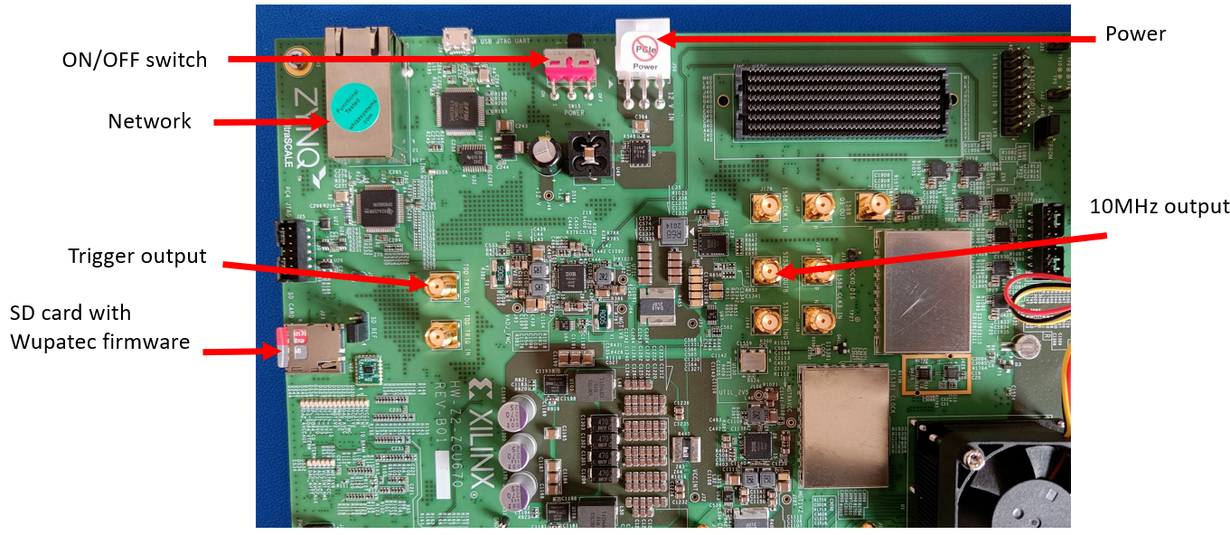
- Trigger and 10 MHz IN/OUT available to connect power meters, multimeter or spectrum analyzer
Board Setup
- Start with the basic assembly ndescribed nhere: Xilinx wiki
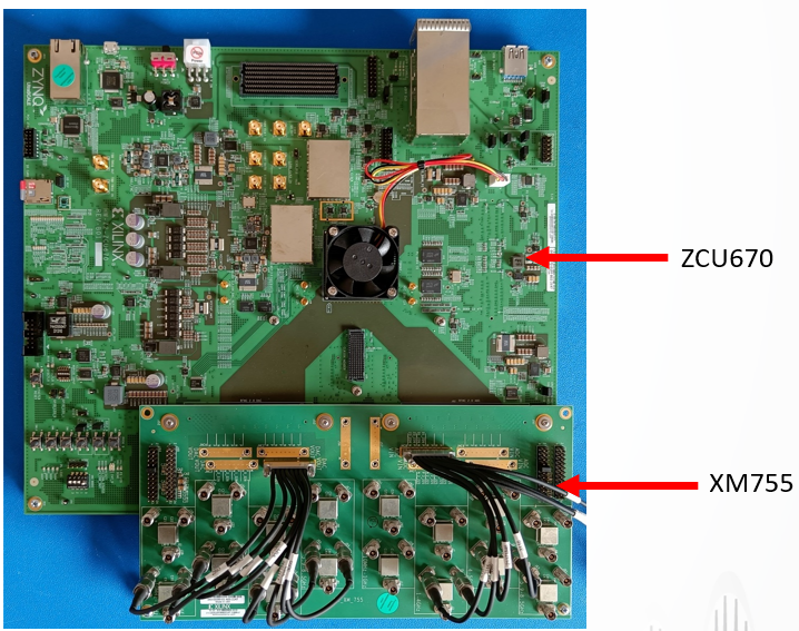
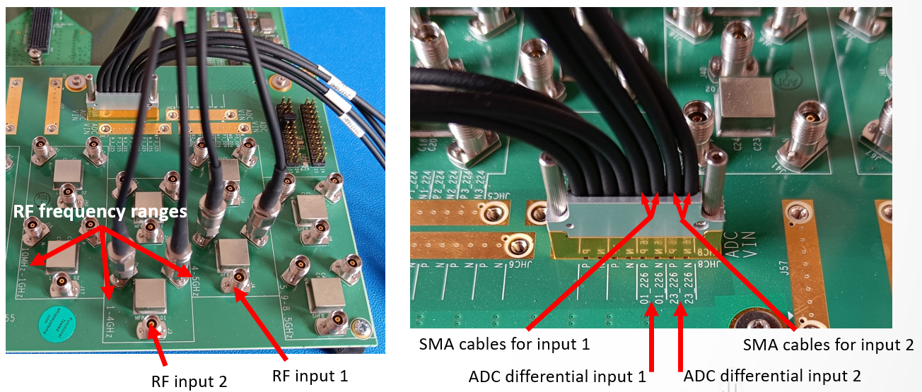
- Connect the HC2-to-SMA cables to locations JHC1 and JHC8 and tighten with
the hex key provided
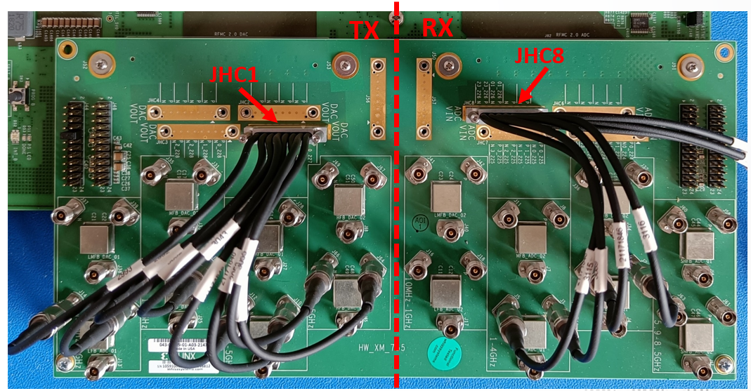
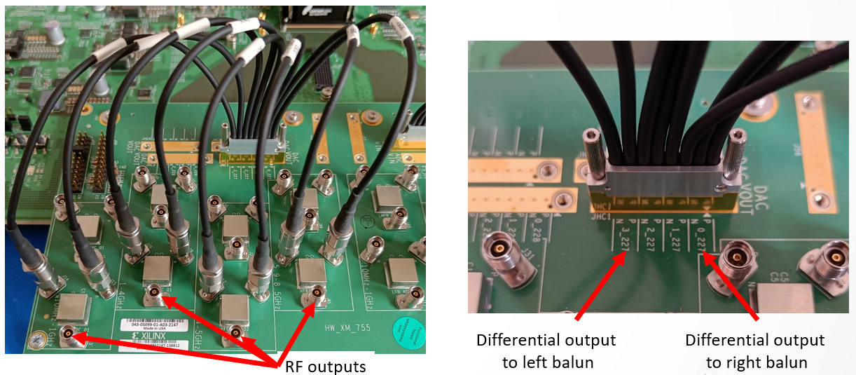
- Connect all the TX SMA cables to the bottom row of baluns.
- Connection in order: connect the left-most SMA cable to the left balun and
the right-most SMA cable to the right balun.Note: Use provided SMA wrench and apply light torque
- Connect the RX SMA cables to the appropriate balun for the targeted RF frequency onto the bottom row of baluns.
- Select on JHC8 the SMA cables corresponding to the differential inputs 01_226 and
23_226.
- Insert the SD card with Wupatec firmware. https://wupatec.com/
- Connect a network cable between the board and host computer.
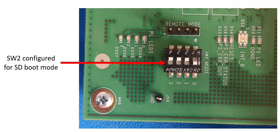
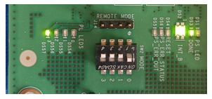
- Change DIP switch SW2 to SD boot mode.
- Connect the power supply and turn on the board power.
- The board powers on and the Wupatec firmware boots from the SD card.
- It takes approximately 30s for the system to fully boot
- Board power up
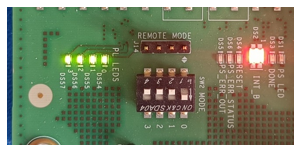
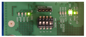
- Boot in progress
- System ready
- Board power up
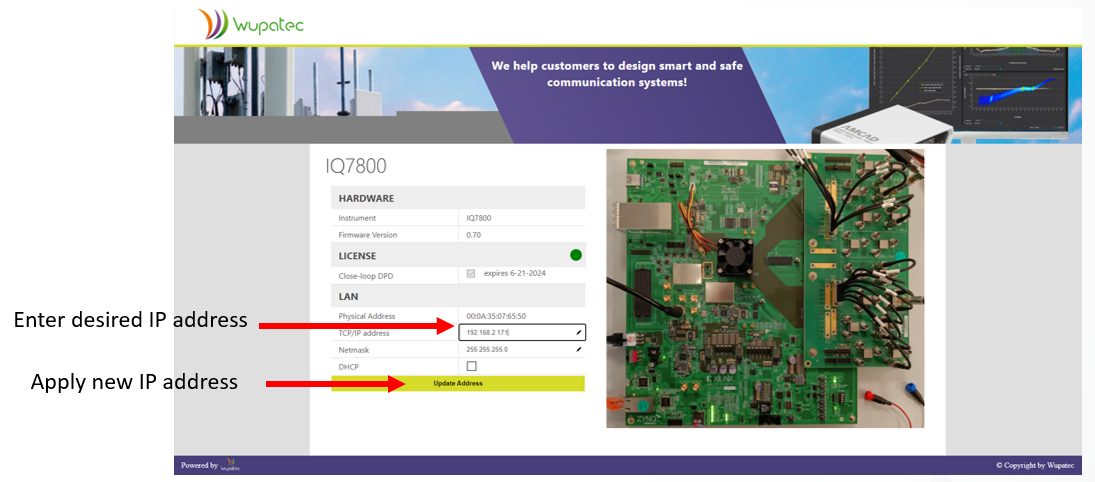
Ethernet configuration
- Default IP address: 192.168.1.170
- Web page available at http://192.168.1.170 to change the IP address.
- The new IP address is saved on the SD card and will be kept between power
cycles.
AMD Xilinx ZCU670 configuration
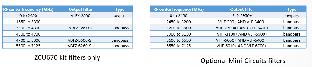
- RF Filters
- RF filters are required on both the TX output port and RF input port to remove unwanted signal images and harmonics
- The optional filters tables offer better signal images and
harmonics rejection than the filters included in the ZCU760 kit
- TX output filters
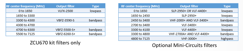
- RX input filters
- TX output filters
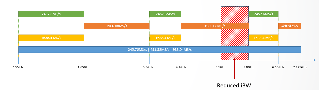
- Sampling rates
-
Standard sampling rate list:
- 245.76MS/s
- 491.52MS/s
- 983.04MS/s
- High sampling rate list:
- 1638.4MS/s
- 1966.08MS/s
- 2457.6MS/s
- Standard sampling rates 245.76MS/s, 491.52MS/s and 983.04MS/s are available across the complete RF spectrum.
- High Sampling rates 1638.4MS/s, 1966.08MS/s and 2457.6MS/s are
available on limited RF bandwidths.
-
Standard sampling rate list:
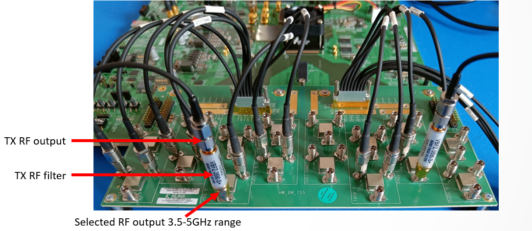
- RF output
- TX RF outputs are all active, select the one corresponding to the
frequency range of your application.
- The balun with the range marked 4-5GHz extends from 3.25 to
5GHz
- The balun with the range marked 4-5GHz extends from 3.25 to
5GHz
- TX RF outputs are all active, select the one corresponding to the
frequency range of your application.
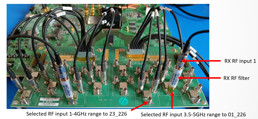
- RF input
- Only one RX RF input is active, connect the SMA cables from JHC8 to
the balun with the frequency range corresponding to your
application.
- The balun with the range marked 4-5GHz extends from 3.25 to
5GHz.
- The balun with the range marked 4-5GHz extends from 3.25 to
5GHz.
- Only one RX RF input is active, connect the SMA cables from JHC8 to
the balun with the frequency range corresponding to your
application.
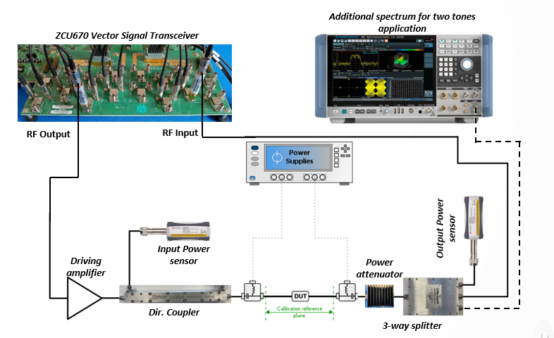
Typical Bench Setup
- All instruments are controlled by IQSTAR for completely automated measurements.
- Aim for +13dBm of peak input power at the RF Input port to achieve measurements with the best dynamic range.
-
The maximum available peak power at the RF output port is between +5dBm
and -2dBm depending on the RF frequency
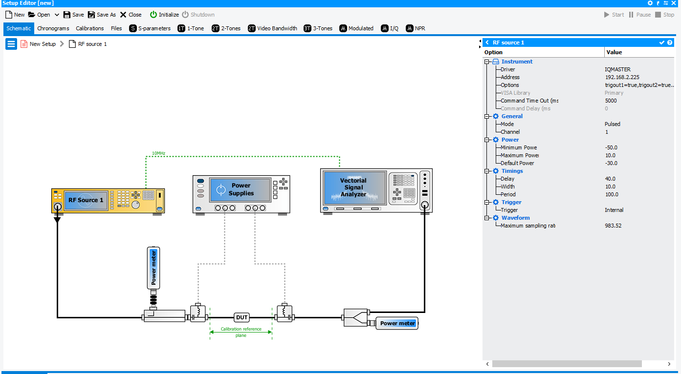
- Calibrations
-
Scalar
Calibration in IQSTAR is available when at least two power
sensors and one RF source are activated in the setup editor. Power
calibration is done in two steps :
- Input power calibration
Input Power Sensor calibration to extract losses between input Power Sensor and Input DUT reference plane
Note: During calibration use a driver amplifier that can’t exceed the power meter maximum input power, even at the maximum TX output power (+5dBm)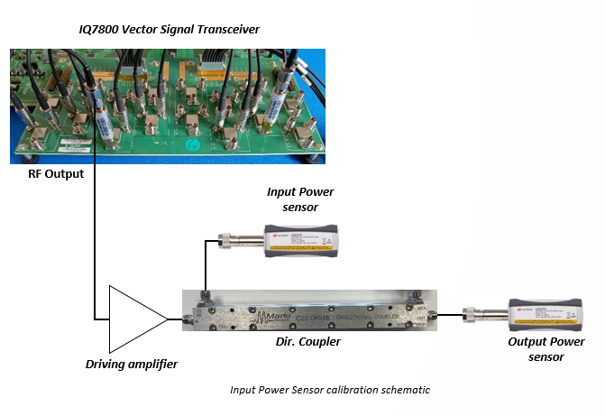
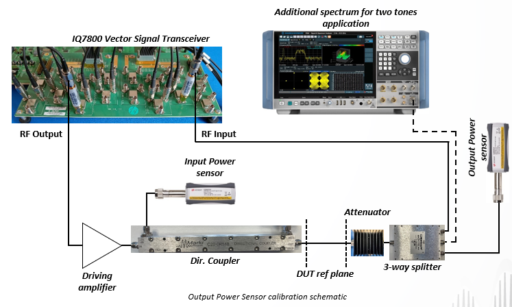
- Output power calibration
Output Power Sensor calibration to extract losses between Output Power Sensor and Output DUT plane using input power calibration
- Input power calibration
-
Scalar
Calibration in IQSTAR is available when at least two power
sensors and one RF source are activated in the setup editor. Power
calibration is done in two steps :
- Pulsed CW setup
- The ZCU670 provides pulsed CW signal in the 10MHz-7.125GHz frequency range to measure power, gain and power added efficiency.
- RF pulse delay, pulse width, pulse period and pulse slope can easily be
adjusted in IQSTAR software.
Note: Verify the voltage compatibility between the ZCU670 trigger output (0V-1.8V) and Power meters/Power supplies trigger inputs.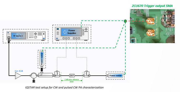
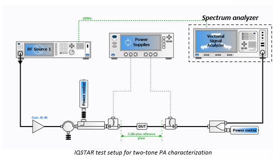
- Two Tones setup
-
Two-tone signal generation for two-tones characterization or to evaluate Power Amplifier video bandwidth.
- Tones spacing can be adjusted in the 1kHz to 1500MHz frequency range.
- The ZCU670 10MHz reference output must be connected to the spectrum
analyzer reference input.
-
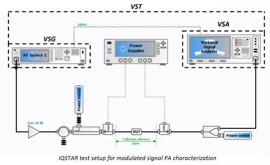
- Modulated signal setup
- The ZCU670 is capable of high-speed and accurate measurements of modulated signals to evaluate Power Amplifier performances with LTE/5G modulation scheme.
- No need for an additional spectrum, the ZCU670 is capable of both generation and acquisition.
- ACPR, EVM and efficiency measurements.
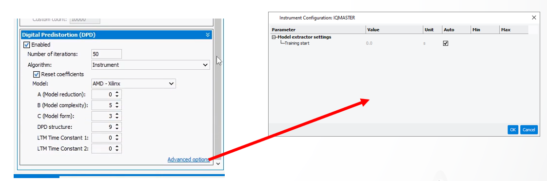
- The test platform can be use with all DPD techniques and algorithms available in IQSTAR to verify that the Power Amplifier under test can be linearized with different levels of DPD complexity.
- Embedded AMD CFR & DPD IP with parameters user-selectable in IQSTAR
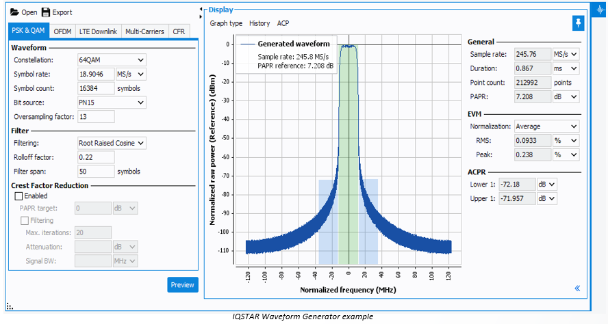
Waveform Generation
Waveform generator embedded in IQSTAR to generate waveforms with modulation scheme from simple PSK & QAM modulation up to LTE Downlink and5G NR Downlink standard test models.
The two main constraints to be considered when configuring the Waveform Generator
are the sampling rate and the waveform length.
- The ZCU670 supports only six sampling rates (see sampling rate list). The waveform generator must be configured properly to generate a waveform with one of these exact frequencies.
- The waveform length (number of points) must be an integer multiple of 16384
points.