
Getting Started : "Overview on the Pulsed Measurement Techniques"
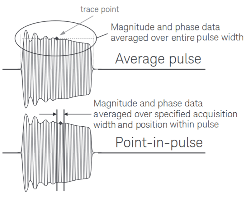
Many devices, particularly power devices, are not designed to operate continuously or with CW signals. This is especially true when devices are being tested on-wafer, where the thermal resistance is greatly increased. In these cases, measurements are best performed in a pulsed test environment. The details of pulsed measurement are greatly dependent on the pulse properties (PRF and duty width) provided by the application studied. Vector Network Analyzers (VNA) are the primary tool for accurate characterization of RF and microwave components, providing precision measurements of both magnitude and phase responses. This note focuses on Point-in-pulse and Average pulse RF measurement techniques using a VNA. Point-in-pulse measurements result from taking data only during a specified acquisition window within the pulse. This window is specified in terms of time duration (width) and position within the pulse (delay). Whereas Average measurements make no attempt to position the trace point at a specific point within the pulse. Each measurement represents the average value of the pulse. There are different ways to do this measurements, depending on the type of detection used : wideband detection (WBF) and narrowband detection (NBF & NBF gated).This note discusses the advantages and disadvantages of these two detection techniques.
Keysight Technologies Pulsed-RF S-Parameter Measurements with the PNA Microwave Network Analyzers Using Wideband and Narrowband Detection App Note
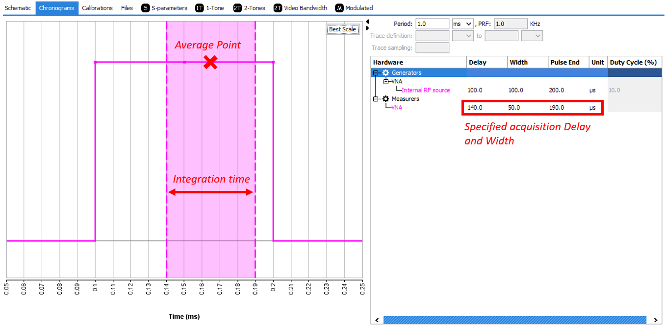
IQSTAR's Chronograms for Point-in-Pulse measurement
Overview of wideband detection (WBF)
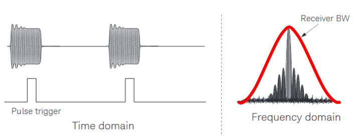
Wideband detection (WBF) is a synchronous detection. In this case, a pulse acquisition trigger is required. The aim is to synchronize with the pulse stream so that data acquisition only occurs when the pulse is in the « ON » state. In this case, the pulsed-RF signal will be demodulated in the instrument, producing baseband pulses.
Keysight Technologies Pulsed-RF S-Parameter Measurements with the PNA Microwave Network Analyzers Using Wideband and Narrowband Detection App Note
In wideband detection, the IF bandwidth has to be high compared to the PulseWidth (=1/Ton) (e.g. : Ton=100 usec => IFBW=1/(Ton) > 10KHz)
Advantages:-
Fast Measurement Speed
-
No loss of dynamic range in function of the duty cycle
- Acquisition window within the pulse is defined. No transient effects take into account (overshoot, rise time, fall time, ringing, ...) => Point-in-Pulse measurement
-
Higher Noise Floor due to the wider IFBW (Dynamic Range = f(IFBW, Averaging) = f(Ton))
-
Pulse Width limitations. As pulse width gets smaller, the spectral energy spreads out – once enough of the energy is outside the band width of the receivers. (e.g.: if Max VNA IFBW=1MHz, minTon = 1usec + jitter)
Overview of narrowband detection (NBF)
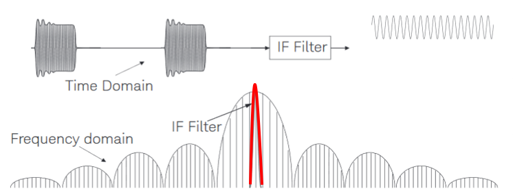
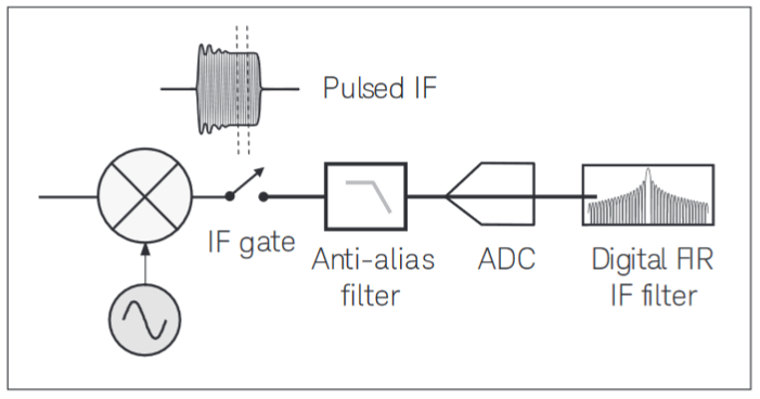
Narrowband detection (NBF) is an asynchronous detection. In this case, a pulse acquisition trigger is not required. The aim is to filter everything away except for one spectral component. With narrowband detection, all of the pulse spectrum is filtered except for the central frequency component. After filtering, the pulsed-RF signal appears as a sinusoidal (CW) signal, so there is no need to synchronize the VNA
Keysight Technologies Pulsed-RF S-Parameter Measurements with the PNA Microwave Network Analyzers Using Wideband and Narrowband Detection App Note
In narrowband detection, the PRF (=1/T) has to be high compared to the IF bandwidth (e.g. : T=1msec => IFBW=1/(20*T)= 50Hz)
-
No lower pulse-width limitations
- Measurement dynamic range is sufficiently high for 1% to 100 % of duty cycles
-
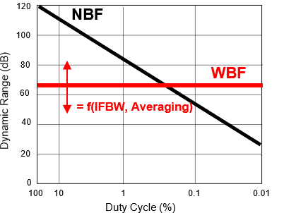
Measurement dynamic range decreases as duty cycle decreases. Average power of the pulses gets smaller, resulting in less SNR (Dynamic range degradation = 20*log(duty cycle)’)
-
Higher PRF is, slower measurement speed will be
- No acquisition windows within the pulse is defined. Possibility to measure wrong results in function of the transient effects (overshoot, rise time, fall time, ringing, ...) => Average Pulse measurement
Overview of narrowband gated detection (NBF gated)
Narrowband gated detection (NBF gated) is based on the same principle than narrowband detection including an IF synchronization. In this case, a pulse acquisition trigger is required. With narrowband gated detection the acquisition window is set with a hardware switch or “gate”,which only allows measurement of a slice of each pulse. The gating is performed on IF portion of the measurement receiver. This makes it possible to increase the measurement dynamics on low duty cycles in comparison with conventional narrow band detection (NBF).
Keysight Technologies Pulsed-RF S-Parameter Measurements with the PNA Microwave Network Analyzers Using Wideband and Narrowband Detection App Note
-
No lower pulse-width limitations
- Measurement dynamic range is sufficiently high for 0.1% to 100 % of duty cycles
- Acquisition window within the pulse is defined. No transient effects take into account (overshoot, rise time, fall time, ringing, ...) => Point-in-Pulse measurement
-
Higher PRF is, slower measurement speed will be
- Only available on Keysigth PNA-X VNA (option S93026B)
Narrow detection (NBF & NBF gated) versus Wideband detection (WBF)
Wideband detection offers dynamic range independent of duty cycle, but there is a limit to how narrow the pulsed stimulus can be. Narrowband detection has no lower pulse-width limit, but measurement dynamic range is proportional to duty cycle. For the pulse widths narrower than 10 us and duty cycle higher than 1%, the narrowband detection offers faster measurement speeds and more dynamic range than the wideband detection.
IQSTAR Pulsed-RF Measurement with a PNA-X (options: 008 & 021 RevA, 025 & 026 RevB)
High-end VNA as PNA-X embedding the RF pulse generator (opt 021) and RF pulse measurement (008) technology to optimize flexibility, minimize trace noise and improve dynamic range. IQSTAR is able to handle and set for user all this advanced capabilities.
Filter Mode: NBF Gated
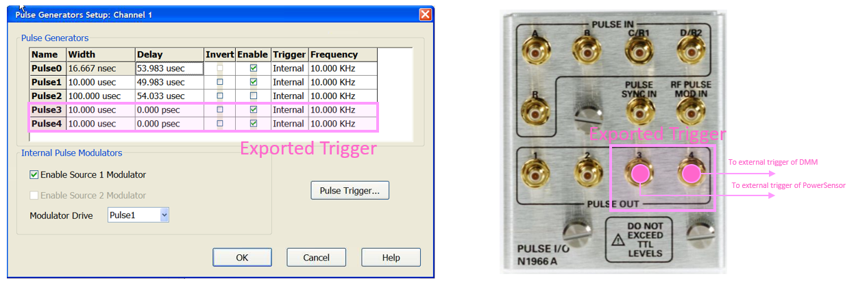
The Narrowband Gated Filter Mode configures the PNA-X internal pulse generators and modulators for measuring pulsed S-parameters or large signal using the narrowband mode detection technique. This mode allows to obtain a high dynamic range as the narrowband mode and also allows to specify an acquisition windows in order to measure an average value during the steady state of the pulse as the wideband mode.
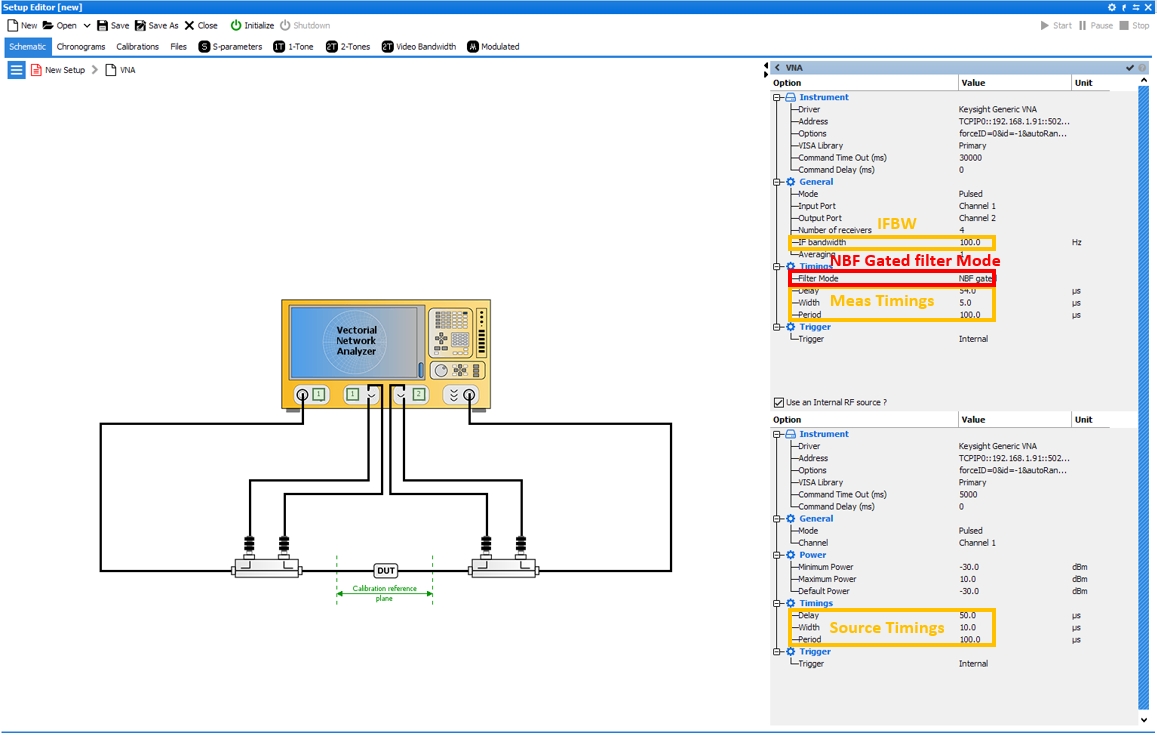
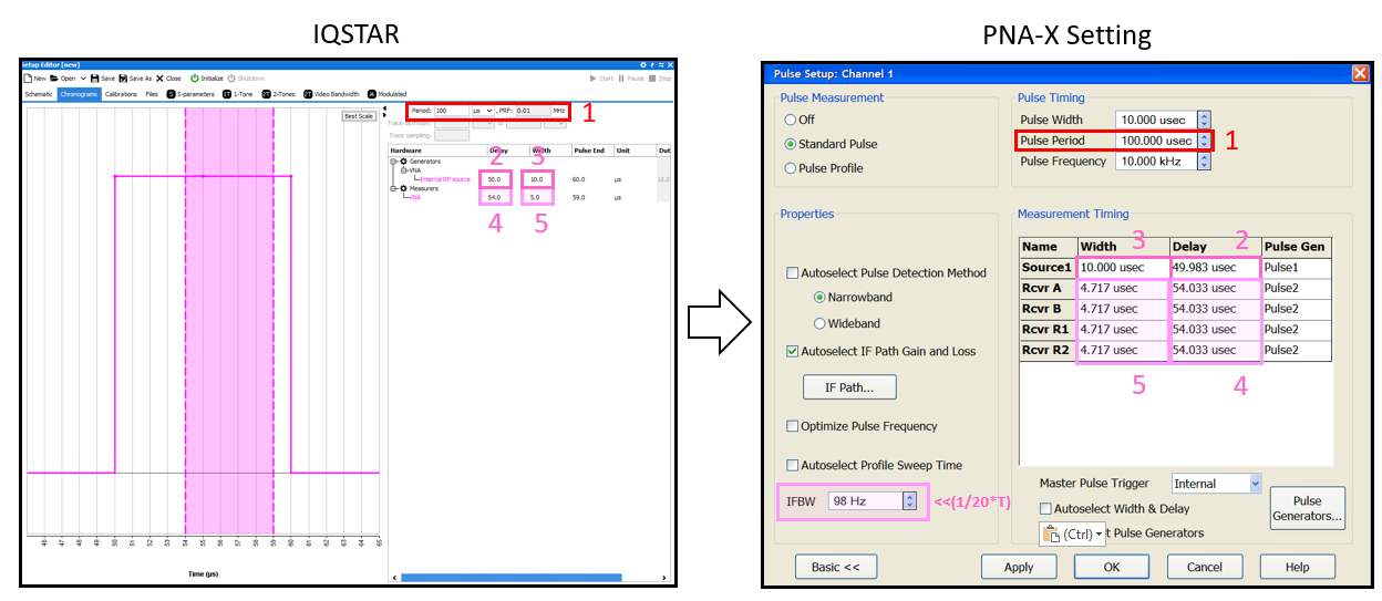
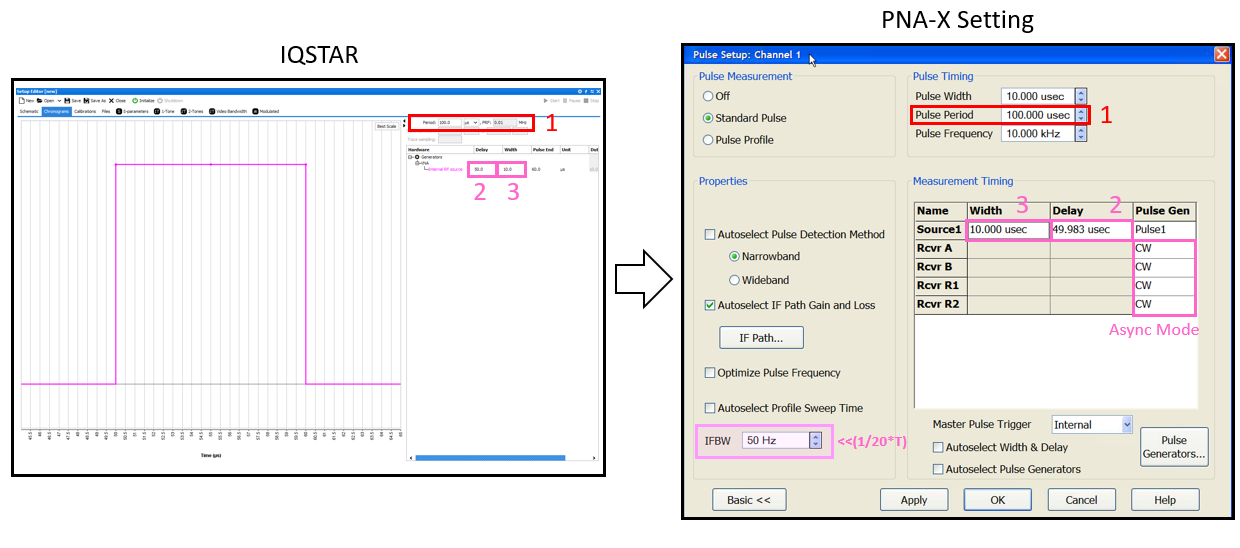
After Initialize Bench, IQSTAR will automatically set the PNA-X in NBF gated mode in order to set and optimize the pulse measurement of PNA-X. As shown below, pulse width, pulse period, delay will be updated and also the IFBW . In this case, the pulse measurement will be turned off in order to work in asynchronous mode compare to the internal RF source to the PNA-X.
Filter Mode: NBF
The Narrowband Filter Mode configures the PNA-X internal pulse generators for measuring pulsed S-parameters or large signal using the narrowband (asynchronous mode) mode detection technique.
In the example below, the NBF filter mode is selected in the Keysight Generic VNA Setup Instruction & Driver Details settings. Then the RF source (internal source of the PNA-X) is set to generate a RF pulse of 10usec width and 100usec period with a delay of 50usec. In this case, only the IFBW setting will define the integration time. As define below, the PRF (=1/T) has to be high compared to the IF bandwidth (e.g. : T=100usec => minimum IFBW=1/(20*T)= 500Hz).
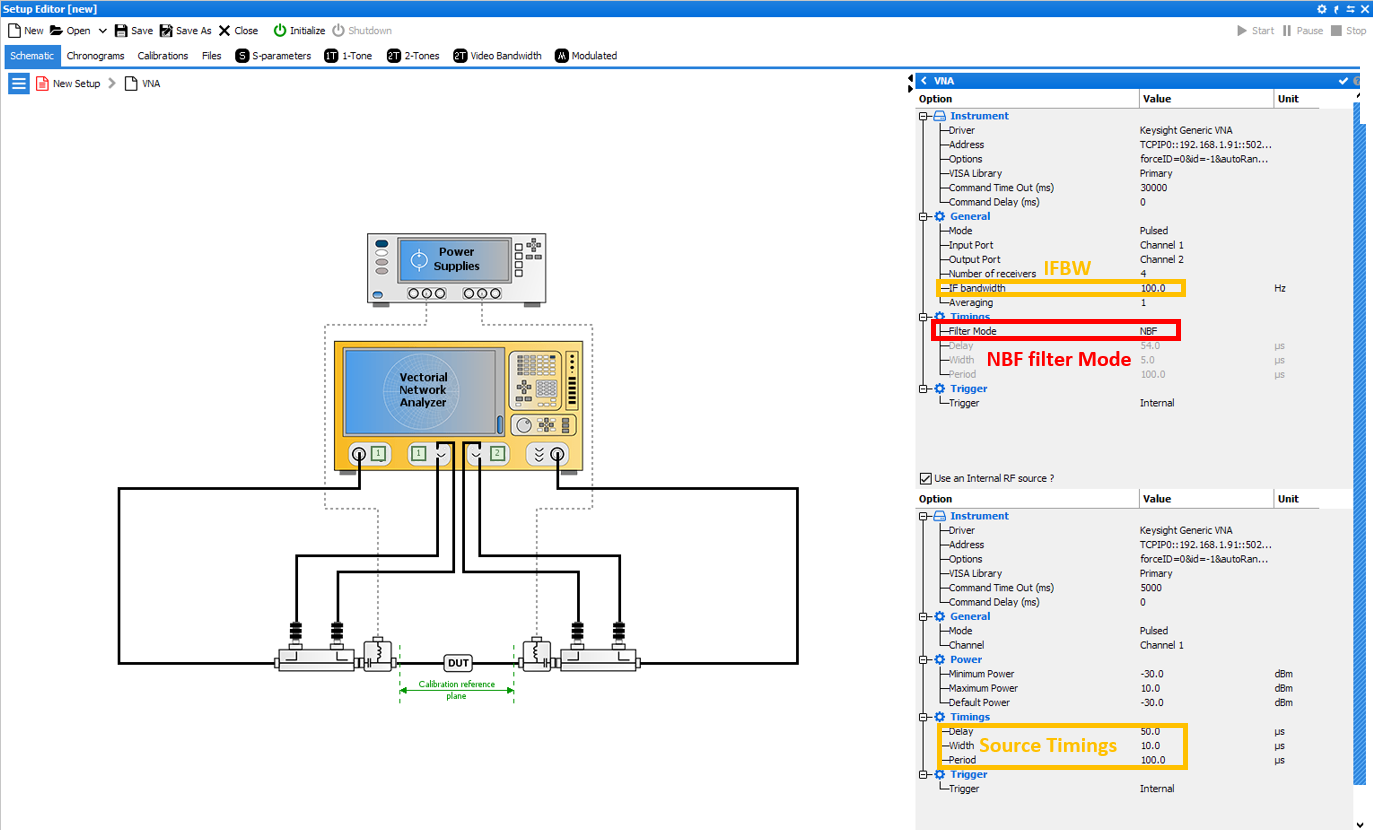
After Initialize Bench, IQSTAR will automatically set the PNA-X in NBF mode in order to set and optimize the pulse measurements of PNA-X. Pulse width, pulse period and delay will be updated. In this case, the receiver measurement will be set in CW mode in order to work in asynchronous mode.
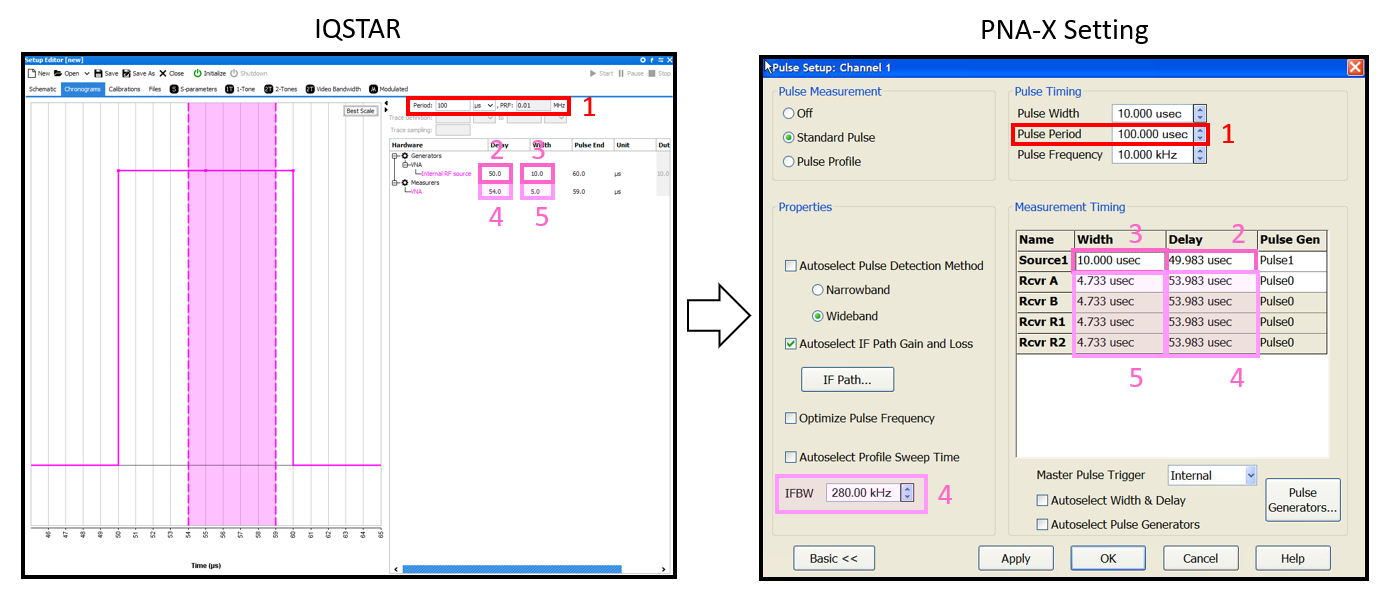
Filter Mode: WBF
The Wideband Filter Mode configures the PNA-X internal pulse generators and modulators for measuring pulsed S-parameters or large signal using the wideband mode detection technique.
In the example below, the WBF filter mode is selected in the Vector Network Analyzer settings. Then the RF source (internal source of the PNA-X) is set to generate a RF pulse of 10usec width and 100usec of period with a delay of 50usec. Whereas the Vector Network Analyzer measurement window is set to 5usec width with a delay of 54usec.
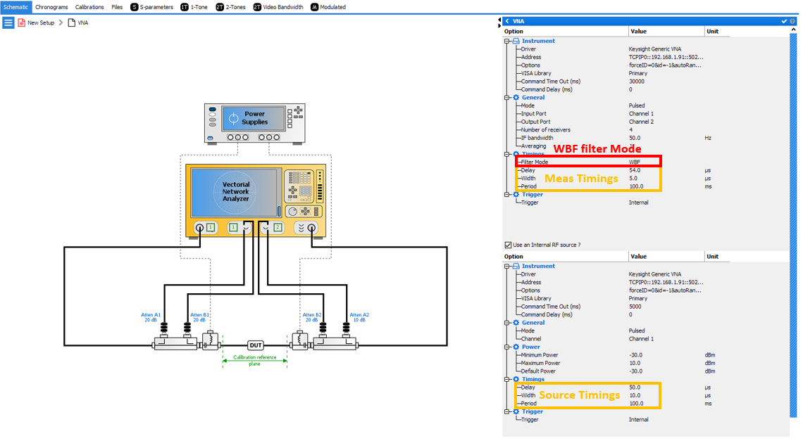
After Initialize Bench, IQSTAR will automatically set the PNA-X in WBF mode in order to set and optimize the pulse measurement of PNA-X. Pulse width, pulse period and delay and also best IFBW (1/5usec + settling time=280KHz) will be updated. As explained before, WBF mode has dynamic range limitation, in order to improve this dynamic range it's advised to add averaging to the Vector Network Analyzer settings of IQSTAR.
IQSTAR Pulsed-RF Measurement with a Basic VNA
- Asynchronous CW mode
For cost-sensitive applications, a VNA without options can be used,with limited flexibility and perhaps increased trace noise and degraded dynamic range due to sub-optimal spectral nulling.
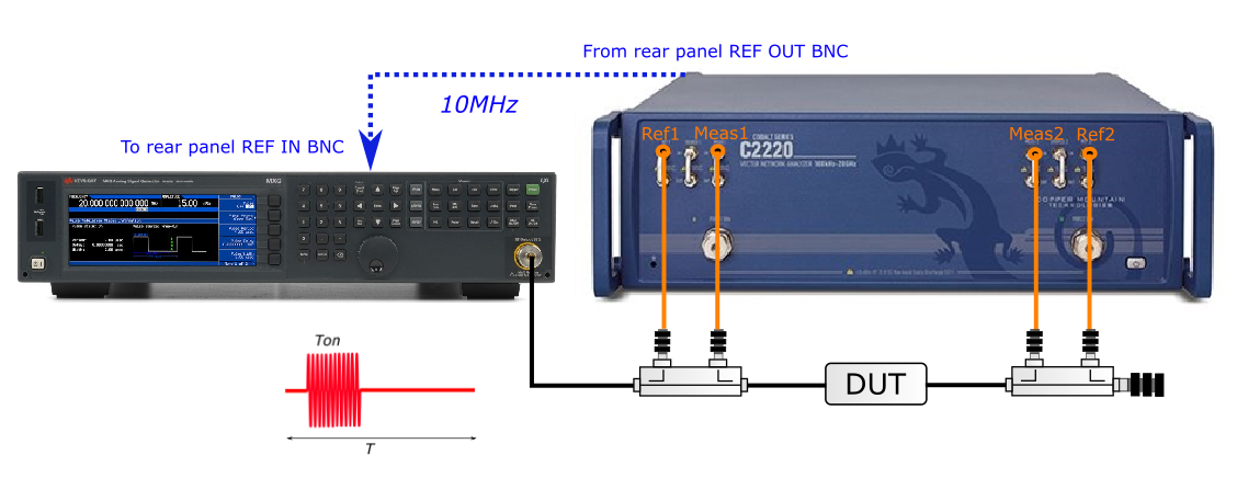
Example:- Setup ExampleThe setup example is based on a VNA with no options for Pulsed-RF measurement (e.g : Copper Mountain C2220), a RF Source including RF pulse generator capability (e.g: Keysight MXG) and a peak Power Meter used for the calibration step (e.g : Keysight N1912A). RF source and VNA are synchronized through the 10MHz reference signal.
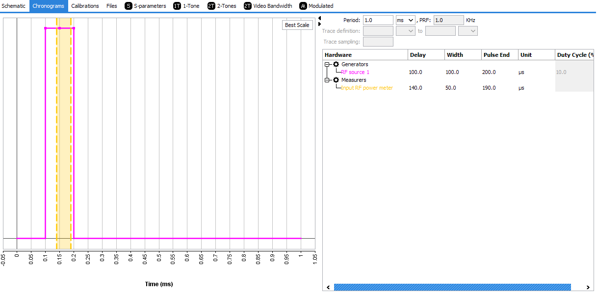
- Timing Example
In this example, the pulse Period will be set to 1 msec (PRF=1KHz) while the pulse Width will be 100 usec (duty cycle = 10%).
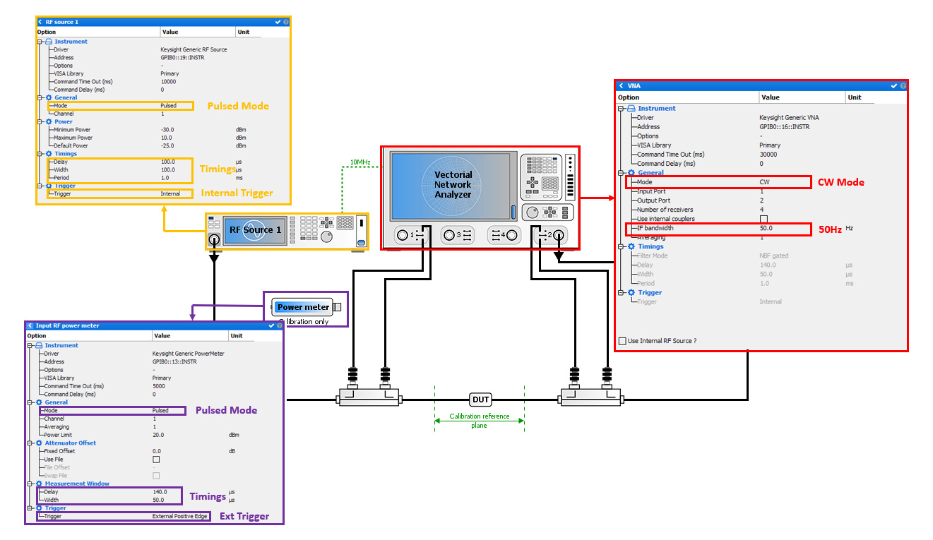
- IQSTAR Setting
In IQSTAR Schematic, select VNA, RFsource1 and Input RF power meter as available instrument.
Vector Network Analyzer settings :- Mode : CW
- IF bandwidth : 50Hz [=1/(20*T)
=1/(20*1msec)]
Note : Depending on the VNA model a higher IFBW can be tried. The maximum cannot exceed [1/(T)] regardless of the VNA model.
- Mode : Pulsed
- Timings : Delay=100usec, Width=100usec, Period=1msec.
- Mode : Pulsed
- Timings : Delay=140usec, Width=50usec.
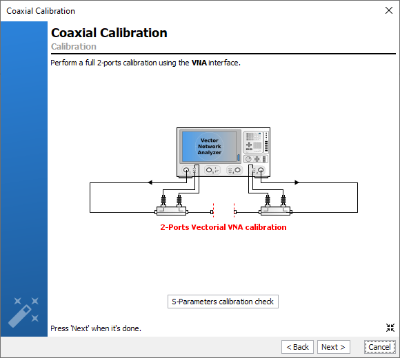
- IQSTAR CalibrationDuring the Vectorial VNA Calibration, the internal VNA source has to be used in order to perform the coaxial 1-ports calibration.
Then during the Absolute Power Calibration, the external RF source and the triggered peak power meter have to be used in order to perform the pulsed absolute power calibration.
- Setup Example
- Synchronous WBF like mode
For cost-sensitive applications, a VNA without options can be used,with limited flexibility and perhaps increased trace noise and degraded dynamic range due to sub-optimal spectral nulling.
- Example:
- Setup Example
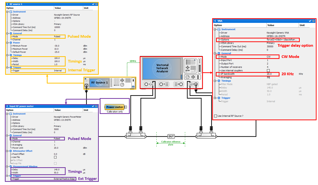
The setup example is based on a VNA with no options for Pulsed-RF measurement (e.g : Keysight PNA N5222B without Option S93025A, S93026A & 021 ), a RF Source including RF pulse generator capability (e.g: Keysight MXG) and a peak Power Meter used for the calibration step (e.g : Keysight N1912A). RF source and VNA are synchronized through the 10MHz reference signal. RF source will trigger VNA pulsed measurement.
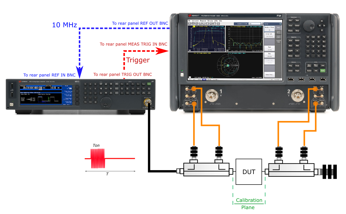
- Timing Example
In this example, the pulse Period will be set to 1 msec (PRF=1KHz) while the pulse Width will be 100 usec (duty cycle = 10%).
- IQSTAR Setting
In IQSTAR Schematic, select VNA, RFsource1 and Input RF power meter as available instrument.
Vector Network Analyzer settings :- Mode : CW
- IF bandwidth : 20KHz [=1/Measurement Windows
Targetted] In this example, measurement
pulse windows targetted is 50 usec. Therefore,
IFBW=1/50e-6=20KHz.Note: Smaller measurment windows is, higher IFBW will be leading to decrease the receivers dynamic range. In this case, averaging should be use to compensate the lake of dynamic.
- Averaging : 50
- In order to handle measurement delay, "Keysight Generic VNA" driver options related to External trigger delay has to be enable
and properly set. To set the specific driver options,
click on
 icon in options from
instrument section.
icon in options from
instrument section.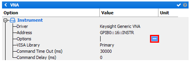
Then select "Enable Exteral Trigger input in CW mode", and set the trigger delay value. In this example 140 usec.
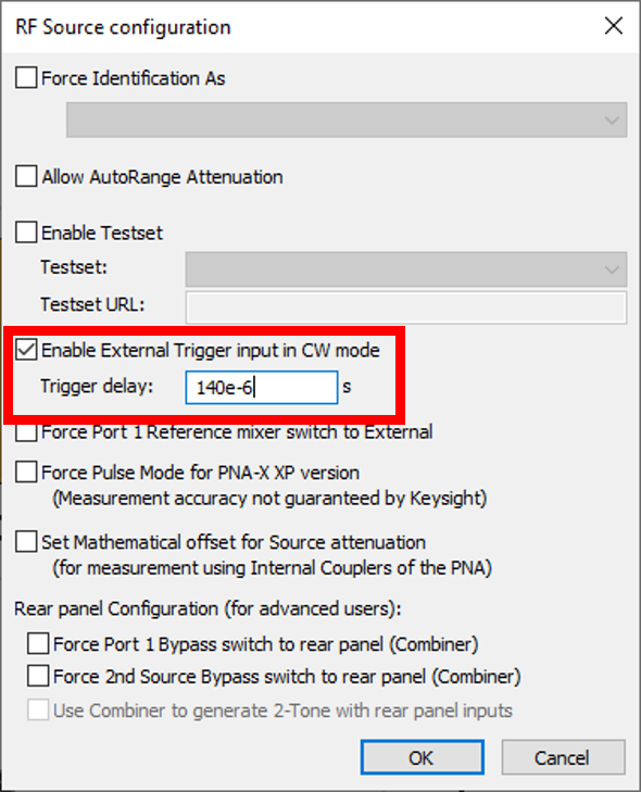
Now, VNA will measurement windows is egal to 50usec and is delayed from 140usec compared to trigger signal.
- Mode : Pulsed
- Timings : Delay=100usec, Width=100usec, Period=1msec.
- Mode : Pulsed
- Timings : Delay=140usec, Width=50usec.
- IQSTAR CalibrationDuring the Vectorial VNA Calibration, the internal VNA source has to be used in order to perform the coaxial 1-ports calibration.
Then during the Absolute Power Calibration, the external RF source and the triggered peak power meter have to be used in order to perform the pulsed absolute power calibration.
- Setup Example