
CW mode B-HF characteristics
This part describes the procedure to follow to extract the Bilateral High Frequency (B-HF) characteristics of a circuit thanks to the VISION Measurement System - Extraction Setup module and measurement equipment in CW mode. At the end of this procedure, a measurement file will be generated and usable for extraction of a B-HF model in VISION Device Modeler.
To begin this task, you will need:
- A licence of VISION Measurement System - Extraction Setup. See Installation and licence setup.
Here are the main steps to follow:
-
Setting up measurement system
-
Measurement system requirements
To perform the B-HF characteristic measurements of a device, two test bench configurations are possible.
- Configuration 1: the following figure shows the
measurement system diagram using a Vector Network
Analyzer (VNA) with access to the receivers. The signal
generator used here is the internal source of the VNA.
The power meter is used for the calibration procedure of
the test bench. The Load tuning station is used to modify
the load impedance seen by the DUT.
Figure: Measurement System Diagram - Configuration 1 
- Configuration 2: the following figure shows the
measurement system diagram using a VNA with access to the
receivers. The signal generator used here is an external
source which can be a RF source or a Vector
Signal Generator (VSG). The power meter is used
for the calibration procedure of the test bench. The Load
tuning station is used to modify the load impedance seen
by the DUT.
Figure: Measurement System Diagram - Configuration 2 
Note: You must check that your measurement system meets the requirements and options for performing measurements in CW mode. For more details, see System measurement options and requirements. - Configuration 1: the following figure shows the
measurement system diagram using a Vector Network
Analyzer (VNA) with access to the receivers. The signal
generator used here is the internal source of the VNA.
The power meter is used for the calibration procedure of
the test bench. The Load tuning station is used to modify
the load impedance seen by the DUT.
-
Measurement system connection
Depending on the configuration, follow the steps below to set up the measurement system:
- Configuration 1:
- Connect the PC (with VISION software installed) with the VNA, the power meter and the load tuning station through LAN, GPIB or USB.
Figure: Measurement System Connections - Configuration 1 
- Configuration 2:
- Connect the PC (with VISION software installed) with the VNA, the RF source (or VSG), the power meter and the load tuning station through LAN, GPIB or USB.
- Connect the 10 MHz OUT port of the VNA with 10 MHz IN port of the RF source (or VSG) using a BNC cable.
Figure: Measurement System Connections - Configuration 2 
- Configuration 1:
-
Measurement system requirements
-
Setting up schematic
Start by creating an extraction setup, see Create extraction setup to accomplish this task. In Setup & measurement tab, click on Setup > Schematic to display measurement system diagram. Configure each instrument of the measurement system:
-
Signal source
Click on Src 1 icon to display the settings. See Signal source 1 for more details.
Figure: Signal Source 1 
Depending on the configuration, follow the steps below to configure the settings:- Configuration 1 (Figure 1) : it is necessary to control the internal source of
the VNA.
- Select RF source.
- Select CW mode.
- In Hardware tab, select the appropriate Driver corresponding to your instrument. Here, it is the driver of the VNA.
- Set Address of your instrument. It can be a GPIB address if the instrument uses VISA, or an IP address if the instrument use a direct LAN connection.
- Click on Test connection for verification.
- Select channel corresponding to VNA's port that will be used as RF source.
- Define power range on which you will use the source, indicating the minimum and maximum power. It is strongly recommended to use the source in its linear operation.
- In Setup tab, set the default power when the RF source is turned on.
- Click on Close to apply settings and return to the schematic tab.


- Configuration 2 (Figure 2): it is necessary to control an external source which
can be an RF source or a Vector Signal Generator
(VSG).
Table 1. Follow the instructions according to instrument type. Instrument type Instructions RF source - Select RF source.
- Select CW mode.
- In Hardware tab, select the appropriate Driver corresponding to your instrument.
- Set Address of your instrument. It can be a GPIB address if the instrument uses VISA, or an IP address if the instrument use a direct LAN connection.
- Click on Test connection for verification.
- Select RF source's channel that will be used during calibration procedure and measurement.
- Define power range on which you will use the source, indicating the minimum and maximum power. It is strongly recommended to use the source in its linear operation.
- In Setup tab, set the default power when the RF source is turned on.
- Click on Close to apply settings and return to the schematic tab.

Vector Signal Generator - Select VSG.
- In Hardware tab, select the appropriate Driver corresponding to your instrument.
- Set Address of your instrument. It can be a GPIB address if the instrument uses VISA, or an IP address if the instrument use a direct LAN connection.
- Click on Test connection for verification.
- Select VSG's channel that will be used during calibration procedure and measurement.
- Define power range on which you will use the source, indicating the minimum and maximum power. It is strongly recommended to use the source in its linear operation.
- Set Maximum sampling rate of the internal waveform generator of the VSG.
- In Setup tab, set the default power when the RF source is turned on.
- In Setup tab, set the default power when the VSG is turned on.
- Click on Close to apply settings and return to the schematic tab.


- Configuration 1 (Figure 1) : it is necessary to control the internal source of
the VNA.
-
Vector network analyzer
- Click on Vector Network Analyzer icon to display the settings. See VNA for more details.
Figure: VNA 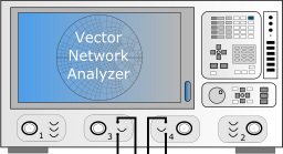
- Select CW mode.
- In Hardware tab, select the appropriate Driver corresponding to your instrument.
- Set Address of your instrument. It can be a GPIB address if the instrument uses VISA, or an IP address if the instrument use a direct LAN connection.
- Click on Test connection for verification.
- Select channel corresponding to the VNA's receiver ports that will be connected with the input and output ports of the DUT.
- In Setup tab, set IF bandwidth.
- Click on Close to apply settings and return to the
schematic tab.


-
Power meter
- Click on Power meter icon to display the settings. See
Power meter for more
details.
Figure: Power meter 
- Select CW mode.
- In Hardware tab, select the appropriate Driver corresponding to your instrument.
- Set Address of your instrument. It can be a GPIB address if the instrument uses VISA, or an IP address if the instrument use a direct LAN connection.
- Click on Test connection for verification.
- Select the power meter's channel that will be used during calibration procedure.
- Set the limit power defined in the instrument specifications.
- Click on Close to apply settings and return to the
schematic tab.

- Click on Power meter icon to display the settings. See
Power meter for more
details.
-
IV power supplies.
- Click on IV power supplies icon to display the settings. See DC power supplies for more details.
Figure: IV power supplies 
Figure: IV power supplies settings 
- Click on
 to allow configuration of the
settings.
to allow configuration of the
settings. - By default, Input and Output are selected to control 2 DC power supplies. You can control up to 4 more DC power supplies by selecting Aux 1, Aux 2, Aux 3 and Aux 4.
- Click on
 in the IV power supply
column corresponding to the DC power supply defined as
Input. A window appears allowing the configuration of
the instrument.
in the IV power supply
column corresponding to the DC power supply defined as
Input. A window appears allowing the configuration of
the instrument.

- Select DC mode.
- In Hardware tab, select the appropriate Driver corresponding to your instrument.
- Set Address of your instrument. It can be a GPIB address if the instrument uses VISA, or an IP address if the instrument use a direct LAN connection.
- Click on Test connection for verification.
- Select the DC power supply's channel that will be used during measurement.
- Select Voltage in Command. By default, the DC power supply will act as a voltage supply.
- In Setup tab, define the minimum and maximum voltage limits (range) on the bias and set Absolute limit current.
- Click on Close to apply settings and return to the IV power supplies settings.
- Disable "Same input and output measurement" option.

- Click on the button in the Measurement column
corresponding to the DC power supply defined as Input. A
window appears allowing the configuration of the
instrument.

- Select DC mode.
- In Hardware tab, select the appropriate Driver corresponding to your instrument.
- Set Address of your instrument. It can be a GPIB address if the instrument uses VISA, or an IP address if the instrument use a direct LAN connection.
- Click on Test connection for verification.
- Select the DC power supply's channel that will be used to measure Voltage and Current.
- Click on Close to apply settings and return to the IV power supplies settings.
- The same procedure can be applied to other DC power supplies. Note: the voltages and currents recorded in the measurement file will only come from the DC power supplies named "Input" and "Output".
- Click on Close to apply settings and return to the schematic tab.
-
Input and output fixtures
- Click on
 to display the settings of Input
and output fixtures. See Input and output fixtures for more
details.
to display the settings of Input
and output fixtures. See Input and output fixtures for more
details.
- Click on to allow configuration of the
settings.
- Click on
 to select your file in the local
file system.
to select your file in the local
file system. - Click on Close to apply settings and return to the schematic tab.
- The same procedure can be applied to the Output fixture.
- Click on
-
Load tuning station
- Click on Load tuning station icon to display the
settings. See Load tuning station for more
details.
Figure: Load Tuning Station 
- Click on to allow configuration of the
settings.
- Select Passive for Tuning mode.
Figure: Load tuning station settings 
- Click on
 . A window appears allowing the
configuration of the instrument.
. A window appears allowing the
configuration of the instrument.
- In Mode tab, select Single mode.

- In Instrument tab, select the appropriate Driver corresponding to your instrument.
- Set Address of your instrument. It can be a GPIB
address if the instrument uses VISA, or an IP address if
the instrument use a direct LAN connection. If this field is
grayed out, click on
 to configure the tuner connection.
See Maury tuners or Focus tuners for more details.
to configure the tuner connection.
See Maury tuners or Focus tuners for more details.

- In Calibration tab, select the calibration file

- Click on Close to apply settings and return to the schematic tab.
- Click on Load tuning station icon to display the
settings. See Load tuning station for more
details.
-
Signal source
-
Setting up calibration
- In Setup & measurement tab, click on Setup > Calibration > New calibration to display calibration wizard. See Calibration wizard for more details.
Figure: Calibration Wizard 
- Select Coaxial power calibration for in-fixture DUT or Unsexed power calibration for on-wafer DUT. Then select where the power sensor to be connected for amplitude power calibration: Source plane or Load plane.
-
Auto de-embedding
- In Setup & measurement tab, click on Setup >
Calibration > Tuner auto
de-embedding
wizard to display calibration wizard. Follow the
corresponding instructions in Perform tuner auto de-embedding. See Tuner auto de-embedding for more
details.
Figure: Tuner Auto De-embedding Wizard 
- In Setup & measurement tab, click on Setup >
Calibration > Tuner auto
de-embedding
wizard to display calibration wizard. Follow the
corresponding instructions in Perform tuner auto de-embedding. See Tuner auto de-embedding for more
details.
-
Performing measurement
In Setup & measurement tab, click on
 .
. Figure: Initialize bench 
-
Tuner manager
The Tuner control tab is displayed once the bench is initialized. See Tuner managerfor more details.
Figure: Tuner manager 
-
DUT biasing
If you have configured DC power supplies, DUT biasing tab opens. We recommend changing the window layout as shown in figure Figure 14, so that it is always visible during the measurement procedure. In the example we will present, we control one DC power supply: Output.
- Click on
 to put your DC power supply into
operation.
to put your DC power supply into
operation. - Set voltage value in Quiescent voltage and click on
 . If you have defined instruments
for IV measurement, you will see the measured values in
Meas. quiescent voltage and Meas. quiescent
current. To update the current and voltage measurements,
click on
. If you have defined instruments
for IV measurement, you will see the measured values in
Meas. quiescent voltage and Meas. quiescent
current. To update the current and voltage measurements,
click on  .
.
Figure: DUT biasing 
- Click on
-
Power sweep
In this section, we want to verify that our measurement bench is compliant for the characterization and that we obtain correctly the specifications of the DUT to model. We will make power sweeps.
- In Select measurement type, choose Power sweep.
- Click on Common and indicate the folder path where to save your data file in Output section. You can add information in this data file relating to the measurement environment and the DUT in Information section.
- In Stop conditions, select Gain compression and set 1 dB. This allows us to define a power range and perform a power sweep without exceeding 1 dB gain compression.
Figure: Power sweep configuration - Common 
- Click on Power sweep and choose what kind of power you
would like to command:
- Raw power corresponds to the applied to the signal generator.
- Calibrated raw power (Psource) corresponds to the power wave A1 at the input of the DUT, calculated from the RF generator raw power calibration. For more details, see Perform RF generator raw power calibration.
- Available input power (Psource) corresponds to the power wave A1 at the input of the DUT, calculated by optimisation
- Delivered input power (Pin) defines the difference between power waves A1 and B1, calculated by optimisation.
- Output power (Pout) corresponds to the power wave B2 at the output of the DUT, calculated by optimisation.
- In Basic, set the power range and the step. Here, we choose Start = -30 dBm, Stop = 10 dBm and Step = 1 dB.
- In Frequency sweep, select in Calibrated frequencies the minimum, maximum and center frequencies.
Figure: Power sweep configuration - Power and frequency settings 
- Click on Load impedance sweep to deploy the panel and
click on
 to configure the load impedance
pattern.
to configure the load impedance
pattern. - Configure the impedance pattern thanks to the wizard. As shown on the following figures, we choose 6 impedances from a circle centered on an impedance of 50 ohms and with a radius of 0.1. The pattern preview is displayed in blue on the Smith chart.
- Click on
 to define the load impedance
pattern in measurement. The pattern is now displayed in red on
the Smith chart.
to define the load impedance
pattern in measurement. The pattern is now displayed in red on
the Smith chart.


- Click on
 to perform measurement. You see the
measurement data on the graphs. At the end of the measurement, a
message informs that the measurement is interrupted when the
gain compression has reached 3 dB for each selected frequency.
to perform measurement. You see the
measurement data on the graphs. At the end of the measurement, a
message informs that the measurement is interrupted when the
gain compression has reached 3 dB for each selected frequency.
Figure: Warning message 
Figure: Power sweep measurement 
- Click on Common and disable Gain compression in Stop conditions.
- Now we have the first characteristics of the DUT allowing us to determine the power range for which you correctly represent the linear gain over a wide dynamic and also to determine the level of gain compression on which the peak power of your application signal in simulation will reach. Click on Power sweep and change Start and Stop values to obtain the optimal representation of the gain for the model.
-
B-HF characteristics
In this section, we will measure the B-HF characteristics for the B-HF model.
- In Select measurement type, choose Bilateral HF characteristics.
- Click on Common and indicate the folder path where to save your data file in Output section. You can add information in this data file relating to the measurement environment and the DUT in Information section.
- Click on Power sweep and choose what kind of power you would like to command: here we choose Raw power.
- In Basic, set the power range and the point count. Here, we choose Pmin = -30 dBm, Pmax = 10 dBm and Point count = 35. The ideal number of points is between 30 and 40 to describe gain compression. The fixed step between the measurement point is calculated from the applied voltage. From the linear distribution of points in tension , we will observe a logarithmic distribution on the measurement in power in dBm.
- In Frequency sweep, select in Calibrated frequencies the frequencies you want to measure.
- Check in DUT biasing window that the DUT is still in the right bias conditions.
- Click on to perform measurement. You see the
measurement data on the graphs. You have 2 graphs available to
display according to your choice the measures listed in the
table Data.
Figure: B-HF characteristic measurement 
- At the end of the measurement, save your data file in .mdat
format.
Figure: Save measurement file 
For more details, see Sweep plan. -
Tuner manager
-
Measurement file
-
File format
The measurements are saved in a particular format readable as a text file. The information, previously listed in the Common tab, is included in the file. We find the measurements of power waves at the input and output of the DUT as well as measurements of voltage and current from DC power supply for each frequency. You can view the measurement data stored in this file using Visualization module. For more details, see Getting started with Visualization.
Figure: Data file 
-
File format