
Interfaces
Main Interface
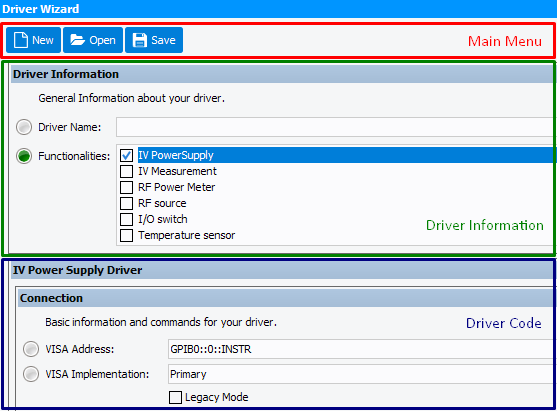
The main window is composed of 3 parts:
- Main menu: basic actions to be performed on the custom drivers.
- Driver information: main information about the driver (name and families)
- Driver codes: contains driver commands. This part depends on selected
families. It is divided in two parts:
- Connection: information about driver connection
- Commands: SCPI commands
Panels are colorized to help user find errors:
- Grey: unspecified and/or untested
- Green: tested and approved
- Yellow: changed but not tested
- Red: unfilled or test has failed
Main menu
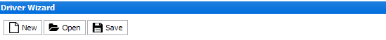
There are three actions:
- New: start a new custom driver
- Open: open stored custom driver
- Save: save the custom driver
Note: If an error message appears during the Save action, the driver will not be
stored. The warning message will not block the action.
Driver Information
This section defines:
- Name: the name of the driver as it will be displayed in setup editor
- Functionalities: families defined by the driver. Following choices made, corresponding panels will appear
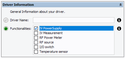
Warning: The driver Name must be the same as the File Name !
Driver Connection Interface
It allows to communicate with the hardware using VISA layer. It is composed
of:
- URL: VISA address of your hardware
- VISA implementation: define the VISA layer to use
- Timeout: time before considering that a command has failed (in milliseconds).
- Identification command: instrument identification. This command is used to test connection in the 'Setup Editor'
- Reset command: reset instrument to a known state
- Initialize command: initialize the instrument
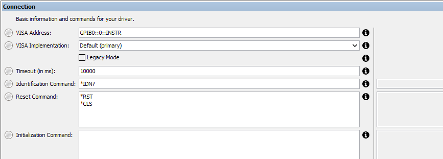
Important: Connection information is required to test SCPI order (URL
and VISA implementation).
Note: This section must be refilled for each selected functionalities.
Driver code
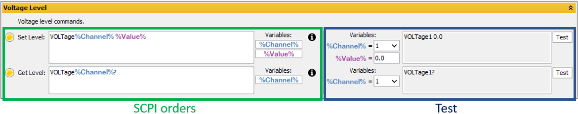
This section is divided in several panels. Each panel is divided in two parts:
- Commands: the left part contains commands
- Tests: the right part is used to test command
Note: Some variables may be needed (e.g. for multiple channel instruments) or mandatory (e.g. voltage level value) for a dynamic use of the driver. These can be added in the command by clicking the corresponding button in the left part, and tested in the right part by changing their values.