
PSK & QAM
PSK & QAM are basic modulation scheme. These simple modulation schemes are easy to use and can be useful to perform envelope transient simulation in System Architect. The available modulation schemes are listed and described in PSK & QAM topic.
The tool follows the algorithm described below to create the PSK & QAM waveform :
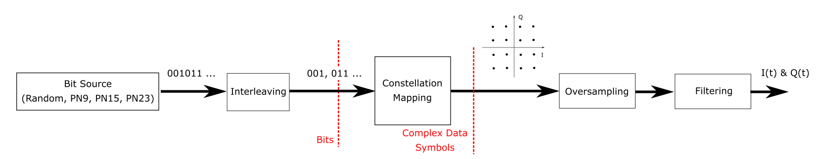
Therefore, the following setting can be set to create the appropriated waveform :
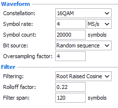
Waveform
- Constellation : Choose the modulation scheme (8PSK, 16QAM, 32QAM, …). To learn more see Constellation.
- Symbol rate : determines the rate (frequency) at which symbols occur in samples per second. Minimum value >0.
- Symbol count : Defines the number symbol in the waveform. Minimum value >0.
Note: If the number of bits generated by the Bit Source isn't
enough to achieve the symbol count, the bit source sequence will be duplicated and
concatenated in order to achieve the symbol count requested.
Example: Bit Source selected is PN9, the number of bits generated will be
29-1 = 512 bits. If the number of Sample count requested is equal to
1000 and the modulation scheme chosen is 16QAM, the number of total bits should be
4000 (1000 x log2(16)). In this case, the tool will concatenate at least eight PN9
sequences in order to achieve 4000 samples.
Note: The value of Symbol count can be automatically adjusted in order to achieve a
finite waveform time length value.
Example: The Symbol Rate requested is equal to 4.3MS/s, the number of
sample requested is equal to 1001 and Oversampling requested is equal to 4.
Therefore, final waveform sample rate will be equal to 17.2MS/s ( Sample Rate =
Symbol rate x Oversampling) and the final waveform number of point will be equal to
4004 (Point Count = Symbol Count x Oversampling). This parameters will lead to a
final waveform time length equal to 232.790698 usec (Duration = 1/Sample Rate x
Point Count). This time length cannot be managed by commercial VSA. In this case,
the tool will automatically udpate the Sample Count to 1032 in order to achieve a
finite waveform time length equal to 240 usec.
- Bit Source : Defines the used bit sequence. To learn more see Bit Source.
- Oversampling : Defines the oversampling factor. The final waveform sampling rate will be equal to Symbol rate x Oversampling (Minimum value > 0).
- Filter: This section allows defining the filtering conditions. To
learn more see Filtering
.
Three settings are available:
- Filtering: filtering the waveform in order to achieve a finite bandwidth and improve the spectral efficiency.
- RollOff Factor: define the filter rolloff (0<RollOff Factor<1.).
- Filter Span: defines the number of symbols truncated (0<filter span).
- CFR:To learn more, see Crest Factor Reduction.