
LTE Downlink
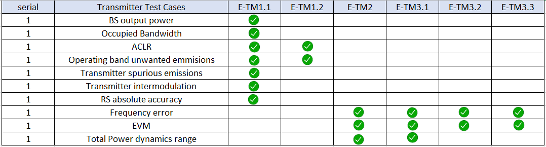
The LTE specifications define conformance test models for transmitter tests. These include transmit signal quality, output power dynamics, Error Vector Magnitude (EVM) for various modulation schemes, Base Station (BS) output power, Reference Symbol (RS) absolute accuracy, etc. The E-UTRA test models (E-TM) are set of signals defined by 3GPP for the radio frequency standard testing of LTE device transmitter chain.
IQSTAR LTE Downlink tool allows to generate easily test models (E-TM) in FDD and TDD operating modes. There are ten test models defined. Each one has the same signal parameters for TDD and FDD, except that the user allocations are different.
The following general parameters of all E-UTRA test models can be setted through IQSTAR.
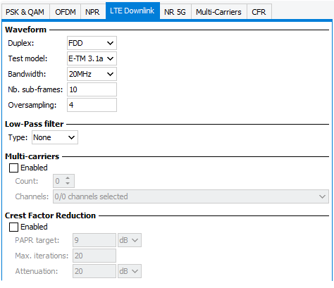
Duplex Mode
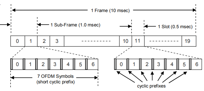
- FDD (Frequency Division Duplexing)Each radio frame is 10 ms long and consists of 10 sub-frames. Each subframe contains two slots and is 1 ms long. Each slot is 0.5 ms long.
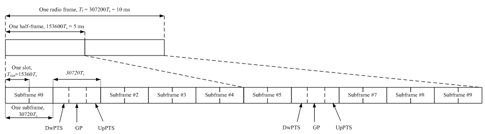
- TDD (Time Division Duplexing)
A TDD frame includes special subframes. A special subframe contains the downlink and uplink pilot timeslots (DwPTS and UpPTS) separated by a transmission gap guard period (GP). These three parts in a special subframe have variable lengths, but the total length is always 1 ms.
Test Model (E-TM)
Different test models are characterised by different parameters such as number of RBs, type of modulation etc. Below is a list of the test models.
- E-UTRA Test Model 1.1
- E-UTRA Test Model 1.2
- E-UTRA Test Model 2
- E-UTRA Test Model 2a
- E-UTRA Test Model 2b
- E-UTRA Test Model 3.1
- E-UTRA Test Model 3.1a
- E-UTRA Test Model 3.1b
- E-UTRA Test Model 3.2
- E-UTRA Test Model 3.3
For testing of radio performance test cases, different E-TM models are used which have been already defined by 3GPP.
Bandwidth (BW)
For each test models six signal bandwidth (BW) are available. Each signal bandwidth has an associated sampling rate and FF size and as shown in the following table.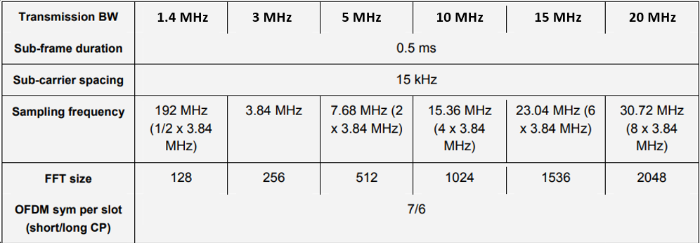
Nb Sub-Frames
Usually, test model (E-TM) are defined on 1 Frame totaling 10 sub-frames. To optimize IQ & DPD measurement speed, Decreasing the number of subframes in the signal, will decrease the waveform number of points.
Oversampling
Defines the oversampling factor. The final waveform sampling rate will be equal to Symbol rate x Oversampling . Minimum value >0. In the case of the DPD application, the oversampling needs to be at least 4 times to ensure DPD efficiency on Adjacent Channel Power Bandwidths.
Filtering
Filtering is used for different application field and optimized for a particular waveform performance:
- Best EVM: An excellent EVM performance while ignoring the effects on ACP
- Best ACP: A combination of an excellent ACP performance and a good
EVM performance

- Custom: Define a custom low-pass filter.


- None: No filter is applied
Multi-carriers
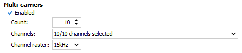
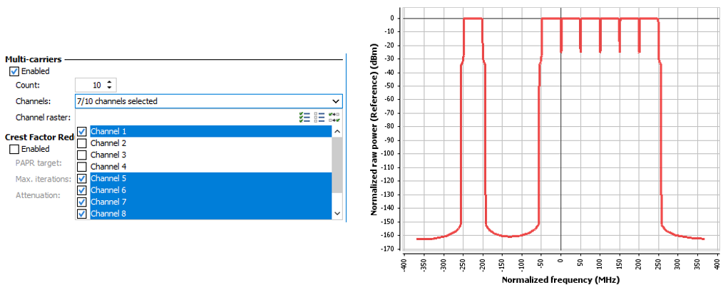
Channel raster defines the spacing between each carrier in multi-carrier operation. The channel raster defines the frequency grid or spacing at which different channels, carriers, or resource blocks are allocated and scheduled within the 5G NR spectrum.
Crest Factor Reduction
Crest Factor Reduction (CFR) is a technique used to reduce the PAPR (Peak To Average Power Ratio) of the transmitted signals so that the power amplifier can operate more efficiently with less back-off. IQSTAR include "Clipping and filtering" CFR algorithms, as described in Crest Factor Reduction.