
5G NR Downlink
5G NR follows the path of LTE by enabling much higher data rates and much higher efficiency for mobile broadband.
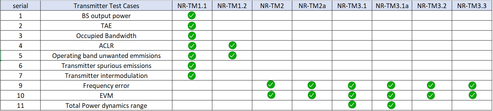
The 5G NR specifications define conformance test models for transmitter tests. These include transmit signal quality, output power dynamics, Error Vector Magnitude (EVM) for various modulation schemes, Base Station (BS) output power, Occupied bandwidth emissions, Adjacent channel leakage ratio (ACLR), etc. The test models (NR-TM) are set of signals defined by 3GPP for the radio frequency standard testing of 5G NR device transmitter chain.
IQSTAR 5G NR Downlink tool allows to generate easily test models (NR-TM) in FDD and TDD operating modes for FR1 or FR2 frequency bands and reach the standardization of transmission bandwidth and subcarrier spacing combinations.
The following general parameters of all test models can be setted through IQSTAR.

Duplex Mode
- FDD (Frequency Division Duplexing) (available only for FR1 frequencies). Each radio frame is 10 ms long and consists of 10 sub-frames.
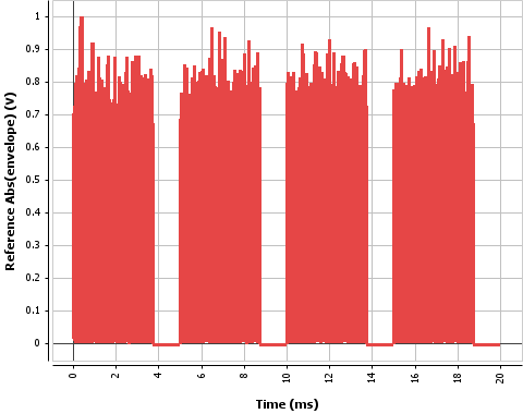
- TDD (Time Division Duplexing) is a burst signal. Each radio frame is 20 ms
long and consists of 20 sub-frames.
Frequency Range
-
FR1 (410 MHz - 7.125GHz)
-
FR2 (24.25 GHz - 52.6 GHz)
Test Model (E-TM)
Different test models are characterised by different parameters such as number of RBs, type of modulation etc. Below is a list of the test models available depending on the frequency range.
-
FR1 (410 MHz - 7.125GHz)
- NR Test Model 1.1 (QPSK)
- NR Test Model 1.2 (QPSK)
- NR Test Model 2 (64-QAM)
- NR Test Model 2a (256-QAM)
- NR Test Model 3.1 (64-QAM)
- NR Test Model 3.1a (256-QAM)
- NR Test Model 3.2 (16-QAM)
- NR Test Model 3.3 (QPSK)
- FR2 (24.25 GHz - 52.6 GHz)
- NR Test Model 1.1 (QPSK)
- NR Test Model 2 (64-QAM)
- NR Test Model 2a (256-QAM)
- NR Test Model 3.1 (64-QAM)
- NR Test Model 3.1a (256-QAM)
For testing of radio performance test cases, different TM models are used which have been already defined by 3GPP.
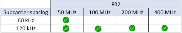
Bandwidth (BW)
Depending on frequency bands (FR1 or FR2) several signal bandwidth (BW) are available.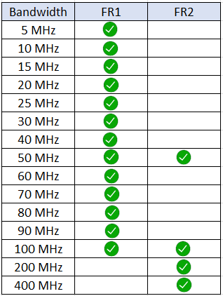
Sub-Carrier spacing
Subcarrier spacing refers to the spacing or frequency separation between individual subcarriers in the Orthogonal Frequency Division Multiplexing (OFDM) waveform used for data transmission.
Comparing to LTE numberology (subcarrier spacing and symbol length), NR supports multiple different types of subcarrier spacing (in LTE there is only one type of subcarrier spacing, 15 Khz). In 5G NR, the subcarrier spacing can vary from 15 kHz to 120 kHz. The larger subcarrier spacings allow for lower latency and support higher-frequency bands, while smaller spacings are suitable for lower-frequency bands and increased coverage.

Nb Sub-Frames
Usually, test model (NR-TM) are defined on 1 Frame totaling 10 sub-frames in FDD and 20 sub-frames in TDD . To optimize IQ & DPD measurement speed, Decreasing the number of subframes in the signal, will decrease the waveform number of points.
Oversampling
Defines the oversampling factor. The final waveform sampling rate will be equal to Symbol rate x Oversampling . Minimum value >0. In the case of the DPD application, the oversampling needs to be at least 4 times to ensure DPD efficiency on Adjacent Channel Power Bandwidths.
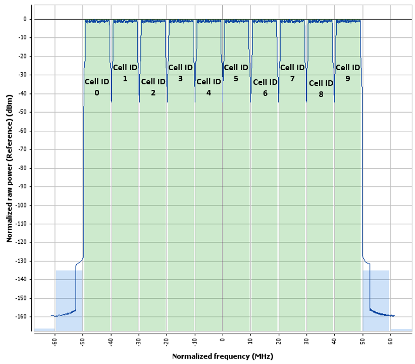
Cell ID
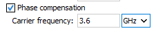
Phase compensation
Unlike LTE, it is possible that 5G NR base station (gNB) and user equipment (UE) center frequencies are different. In this scenario the signal received by UE cannot be decoded. Therefore a phase compensation term can be applied to each OFDM symbol to address carrier frequency offsets and help to estimate and correct phase errors.
Filtering
Filtering is used for different application field and optimized for a particular waveform performance:
- Best ACP: A combination of an excellent ACP performance and a good
EVM performance

- Custom: Define a custom low-pass filter.


- None: No filter is applied
Multi-carriers
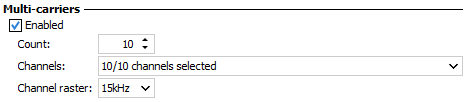
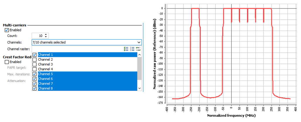
Channel raster defines the spacing between each carrier in multi-carrier operation. The channel raster defines the frequency grid or spacing at which different channels, carriers, or resource blocks are allocated and scheduled within the 5G NR spectrum.
Crest Factor Reduction
Crest Factor Reduction (CFR) is a technique used to reduce the PAPR (Peak To Average Power Ratio) of the transmitted signals so that the power amplifier can operate more efficiently with less back-off. IQSTAR include "Clipping and filtering" CFR algorithms, as described in Crest Factor Reduction.