
Multi-node analysis (DC or Large Signal)
The Frequency response about a periodic steady state solution of a circuit can be obtained as explained in the follwing steps.
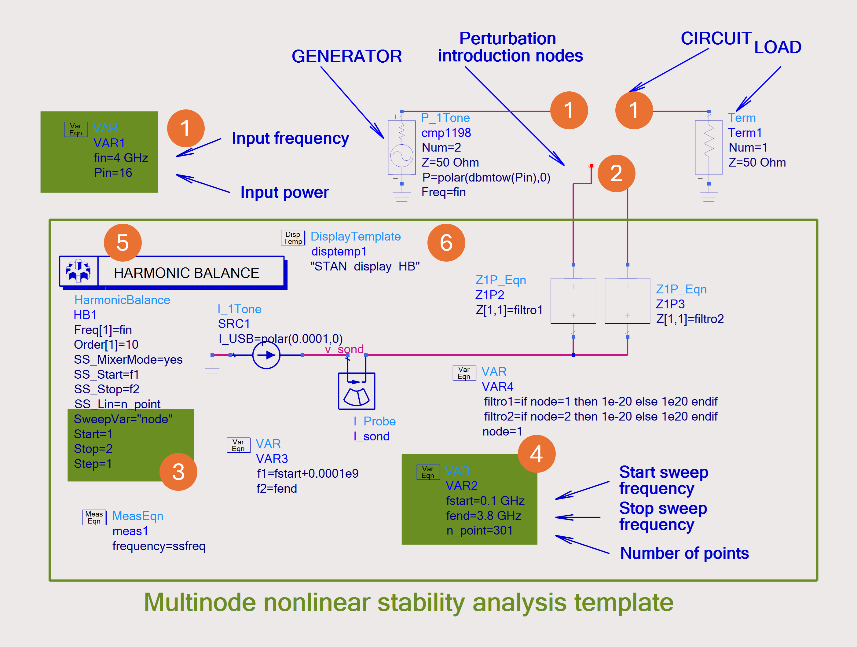
- Introduce the circuit with its particular bias and input drive condition in the template.
- Connect the perturbation source to the nodes to be swept.
- Set up the frequency sweep (initial frequency, final frequency and number of points). The frequency resolution (number of points) can be modified by the user, taking into account the dynamics of his system, in order to have a transfer function sufficiently well sampled.
- Run the Harmonic Balance (HB) (or AC) simulation. Because of the presence of the two sources, this is in fact a mixer like simulation with the unput drive playing the role of the LO and the small-signal current source being the RF.
- Once the simulation is finished, the data display "STAN_display" or "STAN_display_HB" template appears. The table containing magnitude and phase of the transfer function will be exported and the file will be later read by STAN Tool.