AWG-VS
Description : this is a block that allows to simulate an arbitrary waveform generator. This source is mainly used in transient simulation mode, see Simcontroller.
-
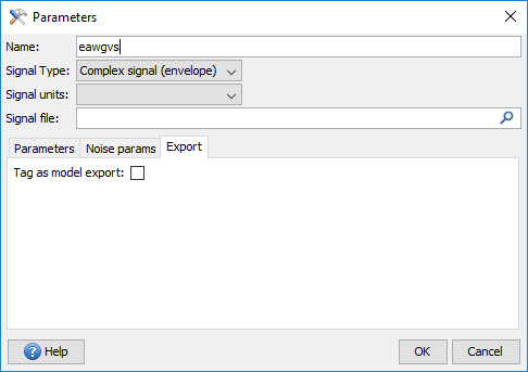
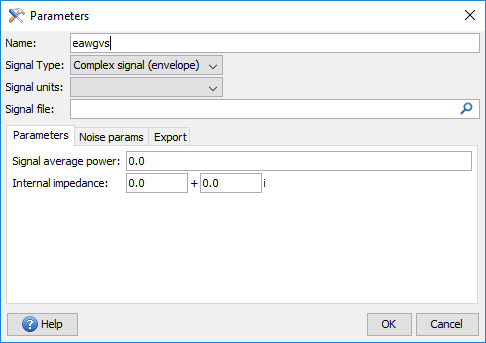
Signal type : allows to configure the output signal as complex or real
- Signal unit : specify the signal record average power control ; dBm : the signal record will be affected an average power in dBm; Rms Volt: the signal record will be affected an average power in RMS volt; Original data : no average power control, the amplitude of the exact signal record is affected a scale factor
- Signal average power : signal average power (in unit above) or scale factor
-
Internal impedance : internal impedance of the source
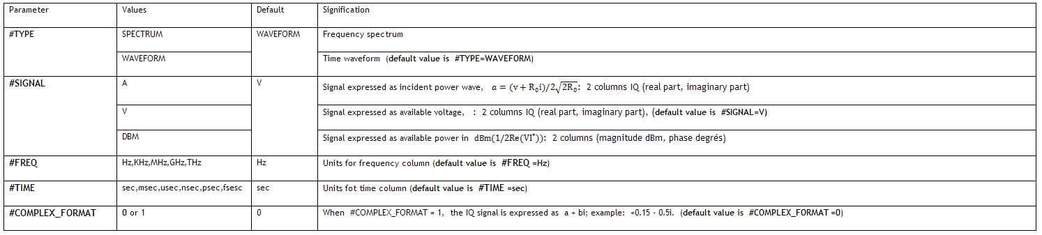
- Signal file : file containing the signal record; see format below
File is made of an identification header and a data body. Data may be signal time domain IQ waveform or frequency spectrum; the type is specified in header. File may contain 2, 3 or more columns. If a time record is present in file, it must be the leftmost column. In absence of time record, file must contain only 2 columns (time domain I,Q). For frequency domain data, file must at least contain 3 columns (Freq, Mag, phase). Frequency axis data must be the leftmost column.
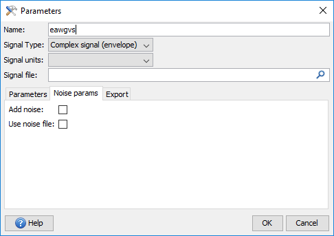
- Add noise : validate in order to take into account the noise file.
- Use noise file : user can add one NF file versus frequency in order to take into account the noise of the source.