
Video Bandwidth Measurement Panel
Video Bandwidth measurement panel is composed of one main parts. Most of the items, as measurement file and information, are similar to 1-Tone measurement.
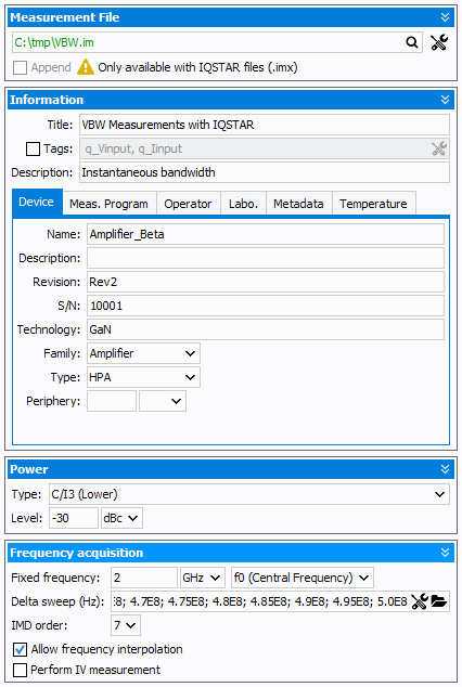
- Power:
- Type: the power sweep may be of different types:
- Raw power: Total raw power. IQSTAR will divide the value
by two (in Watts) in order to send the command to both RF source
(Ptotalraw=PrawSRC1+PrawSRC2)Note: If Driver Amplifier is defined in the schematic, the power defined will take into account the driver amplifier offset set in the schematic.
- Raw power (calibrated): Total raw power calibrated. Available if the Raw Power Calibration has been performed. There is no optimization but the power is offset from the Raw Power Calibration coefficients
- Total available input power: the total available power is optimized at the input of the DUT (Pin_avs_total=Pin_avs_@f1+Pin_avs_@f2)
- Total delivered input power: the total delivered power is optimized at the input of the DUT (Pin_del_total=Pin_del_@f1+Pin_del_@f2)
- Total output power: the total output power is optimized at the output of the DUT (Pout_total=Pout_@f1+Pout_@f2)
- C/I3 (Total, upper, lower): IQSTAR will automatically optimize the input power in order to meet the C/I3 level defined
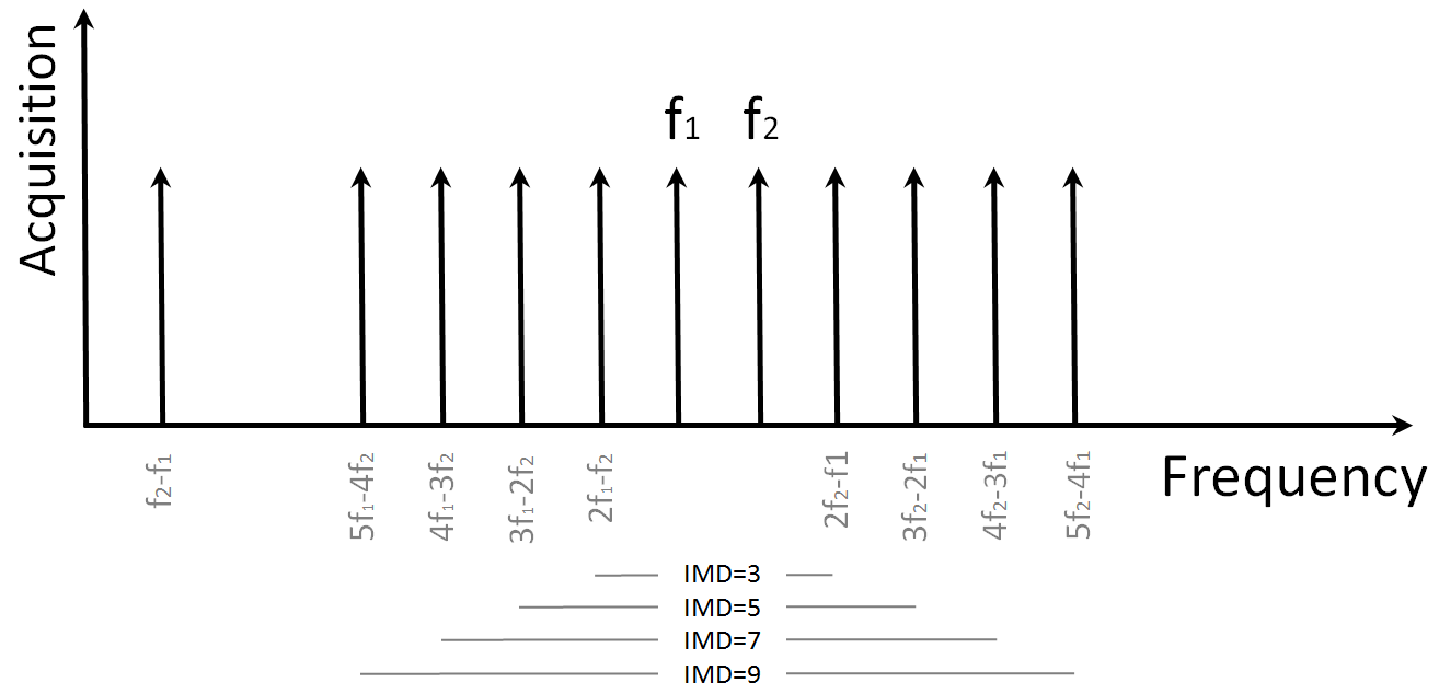
- I3 (Total, upper, lower): IQSTAR will automatically optimize the input power in order to meet the I3 level (power at 2f1-f2 or 2f2-f1) defined
- Raw power: Total raw power. IQSTAR will divide the value
by two (in Watts) in order to send the command to both RF source
(Ptotalraw=PrawSRC1+PrawSRC2)
- Level: set the data level to achieve
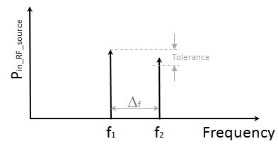
Note: It's important to note that the input powers at f1 and f2 are balanced in order to compensate the dispersive effects of the external passive components or driver amplifiers. IQSTAR embeds its own 2-tones optimizer and the tolerance and number of iterations could be configured in the schematic main option. - Type: the power sweep may be of different types:
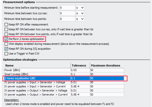
From this panel, select whether the 2 tones have to be balanced and what is the 'Maximum
iterations' of this optimization and the acceptable tolerance (with f1 as the
reference):
- Frequency acquisition:
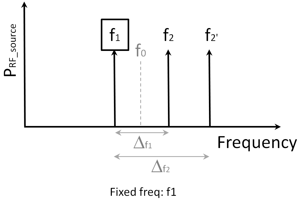
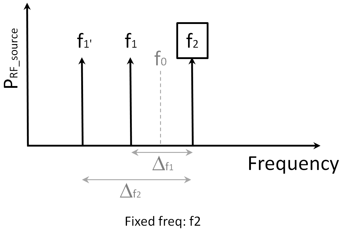
- Fixed frequency:
- Set the frequency value that is used as reference for the delta sweep
- Set if the reference is the central frequency (f0), f1 (lower
carrier) or f2 (upper carrier)
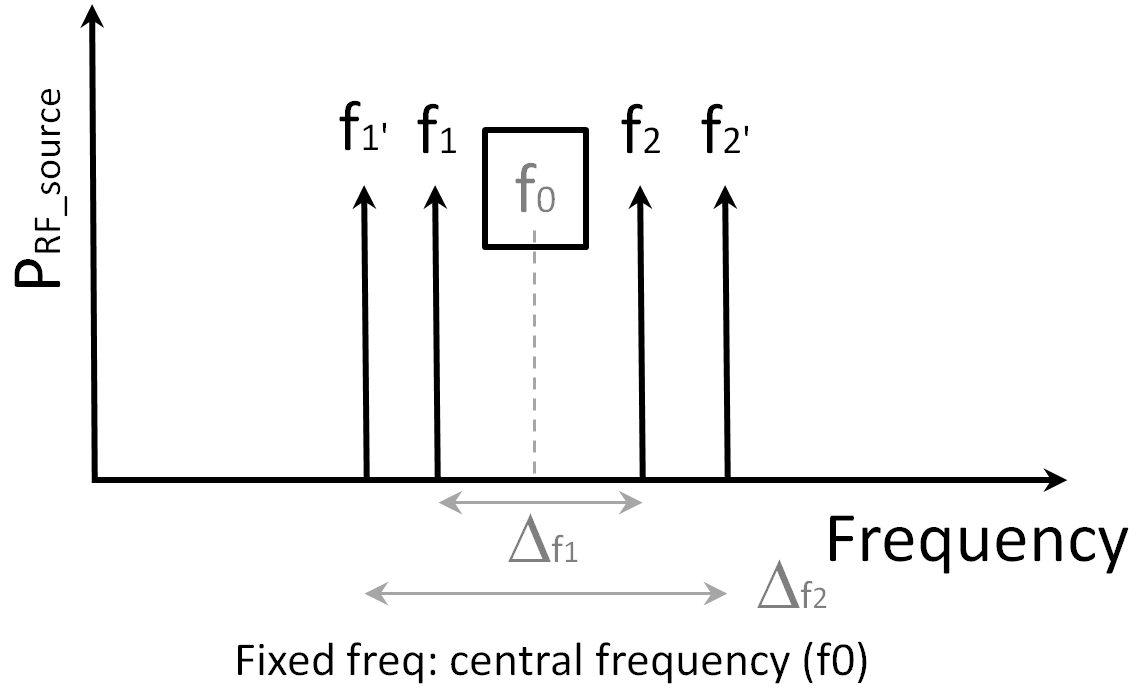
- Delta sweep (Hz): use
 icon to modify the list of the delta frequency sweep
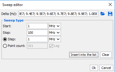
- IMD order: select the IMD order to record (from 3 to 9)
- Allow frequency interpolation: if the list of RF stimulus frequencies is different from the calibrated one, IQSTAR will interpolate the errors terms
- Perform IV measurement: disable this option in order to prevent the IV measurement and to speed-up the measurement process
- Fixed frequency: