
1-Tone Measurement Panel: Sweep Settings
Sweep setting is used to define two or three nested loops sweep in function of power, frequency and VSWR using different acquisition mode.
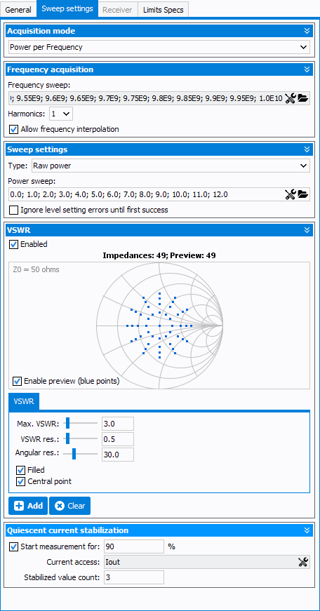
Acquisition mode:
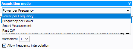
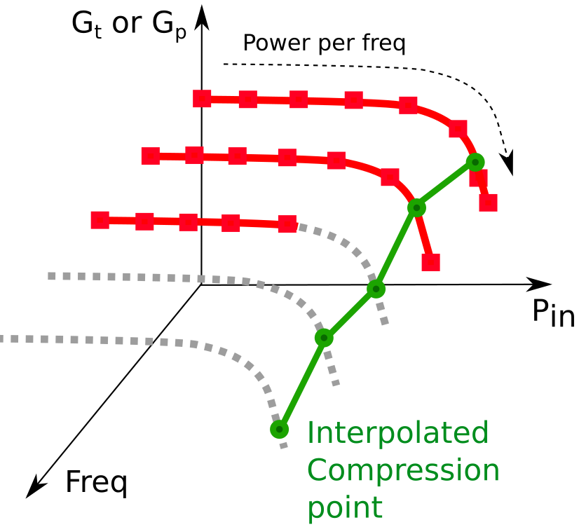
- Power per Frequency: for each frequency acquisition, a ramp of RF power
will be sent to the DUT.
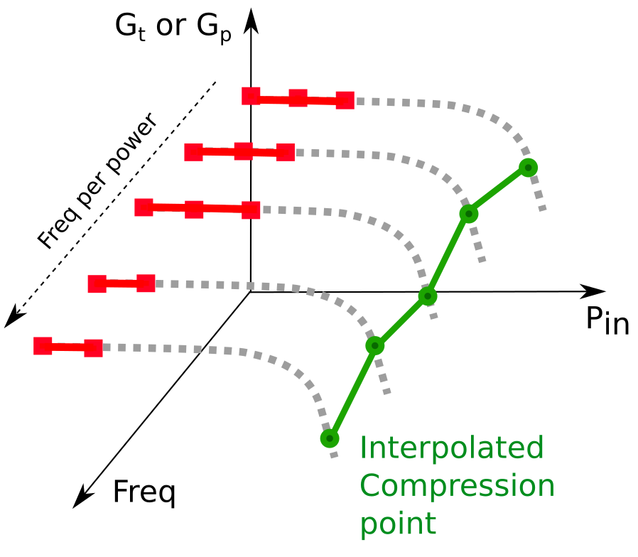
- Frequency per Power: for each power, the acquisition is done for all
frequencies.
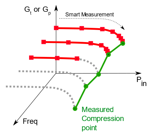
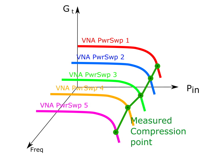
- Smart measurement is an advanced power per frequency mode. The ramp of
power is not linear but adaptive to achieve a targeted value.
- Fast CW is a sweeping method that can be used to improve the measurement
speed. Contrary to the classical power sweep where IQSTAR is sweeping the VNA
power, the VNA is here asked to sweep the power for a fixed frequency, asking
the instruments to bufferize the measured values, and resulting in a great speed
improvement.DANGER: When using this type of sweep, the measurement stop conditions will not be verified because of the VNA sweeping entire power sweeps. The DUT will not be under IQSTAR protection and measurement can lead to damages. It is important to know the limits to not exceed in this case.
For more informations about how to setup a Fast CW bench, see Getting Started : "Fast CW measurements".
Fequency Sweep Settings

- Frequency sweep (Hz): the calibration frequency list will be set by
default. Click on
 icon to open the 'Frequency editor' and modify the
frequency listNote: 'Frequency editor' is a tool used to define frequency sweeps or frequency segments. Click on 'Clear' or 'Inject into list' to add or remove frequencies. It is possible to select the frequencies available in the selected calibration file by clicking on 'Select frequencies from calibration'. It's also possible to save or load a frequency list (*.freq files) using
icon to open the 'Frequency editor' and modify the
frequency listNote: 'Frequency editor' is a tool used to define frequency sweeps or frequency segments. Click on 'Clear' or 'Inject into list' to add or remove frequencies. It is possible to select the frequencies available in the selected calibration file by clicking on 'Select frequencies from calibration'. It's also possible to save or load a frequency list (*.freq files) using icons.
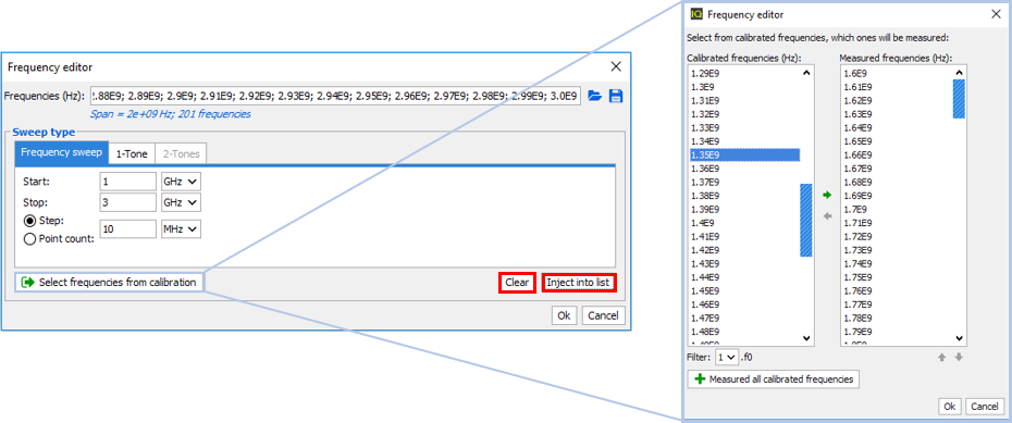
- Harmonics: set the number of harmonics to measure (1 to 4)
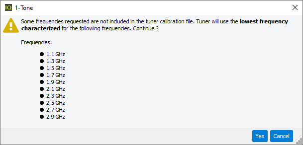
- Allow frequency interpolation: if the list of RF stimulus frequencies is different from the calibrated one, IQSTAR will interpolate the errors terms
Power Sweep Settings:
Sweep settings configurations depend on the acquisition mode selected:If 'Power per Frequency' or 'Frequency per Power' is selected:

- Type: the power sweep can be of different types:
- Raw power: the power is not optimized, IQSTAR only send the
command to the RF sourceNote: If Driver Amplifier is defined in the schematic, the power defined will take into account the driver amplifiers offset set in the schematic.
- Raw power (calibrated): available if the Raw Power Calibration has been performed, there is no optimization but the power is increased by an offset from the Raw Power Calibration coefficients
- Available input power: the available power is optimized at the input of the DUT
- Delivered input power: the delivered power is optimized at the input of the DUT
- Output power: the output power is optimized at the output of the DUT
- Raw power: the power is not optimized, IQSTAR only send the
command to the RF source
- Ignore level setting errors until first success: if there is a power optimization, IQSTAR moves to next power level if the optimisation does not reach the previous target
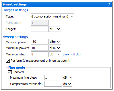
- Target settings
- Type: select the target to reach (it could be a gain compression or a power level)
- Point count: (available only in linear gain compression mode) set the number of point to compute the average level of the linear power
- Level: set the target level to reach
- Sweep settings
- Min/Max power: set the power range authorized for the optimization
- Maximum step: set the maximum power step achievable between two
pointsNote: When the gain compression is selected as target, the algorithm is based on the gain slope. First step will be equal to the maximum step, then this step will decrease in function of the gain slope value.
- Perform IV measurement only on last point: check this box in
order to speed up the measurement by measuring the IV performance only
at the target level and not for each power levelNote: In this case, no post measurement interpolation will be possible.
- Fine mode
Basic mode using coarse step can lead to an overdrive of the DUT.
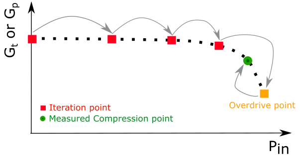
With the fine mode, more iterations are used as the gain becomes closer to the target compression point, which minimizes excess drive power.
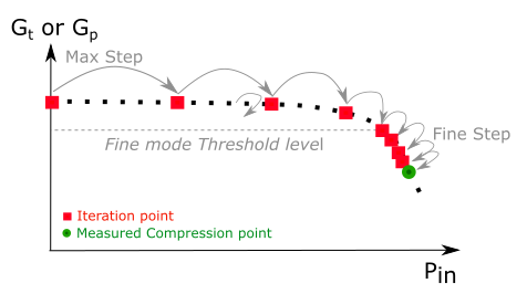
- Maximum fine step: define the maximum step size achievable when the threshold of fine mode is reached
- Compression threshold: set the value of gain compression to trigger fine mode
VSWR
In order to affect on purpose the DUT, it is possible to control a load tuner and change the load impedance of the DUT. The pattern consists of impedance points that are 50-Ohms centered. If this VSWR module is enabled, the tuner will be initialized before the measurement begins.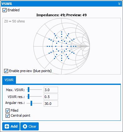
- Enable preview (blue points):set active the preview in the smith chart. Red points are already added, blue are the current ones being set up.
- Max VSWR: pattern max VSWR
- VSWR res.: pattern VSWR resolution
- Angular res.: pattern VSWR angular resolution
- Filled: if check, the pattern is filled with points distance of VSWR resolution value. If unchecked only the circumference points will be active.
- Central point: activates the 50 Ohms point if checked.
Fast CW settings (Available with Fast CW only):
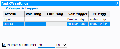
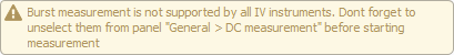
If the used IV multimeters are compatible with burst measurements, instrument measurement ranges will need to be selected in this table. If some instruments do not have this burst capability, please refer to DC Measurement. Triggers also needs to be defined and are positive edge by default.
Minimum setting time: sets a delay between the VNA power sweep points. Can be used to achieve a DUT steady state before measuring a value.
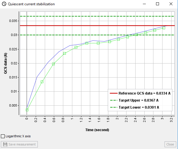
Quiescent current stabilization (Available with Power per Frequency, Smart and Fast measurements):
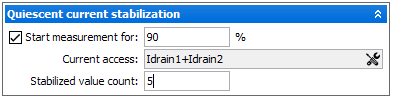
- Start measurement for: set the level (in % of initial value) of quiescent current to be reached before a new sweep can start
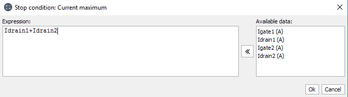
- Current access: choose the current access to apply the conditionNote: It is also possible to create an expression in order to define a custom current (e.g. sum of two currents).
- Stabilized value count: set the number of consecutive measurements that
must be within the toleranceWhen 'Quiescent current stabilisation' is enabled. An additional window will pop up during measurements to display the quiescent current value, the reference current level and the current tolerance. This curve can then be saved in a file if needed.
Related Information: