The “EM Link” module provides a suitable bridge between the functionalities offered by VISION and those offered by an electromagnetic simulator. For example, Vision can export the
amplitude and phase of the signal emitted by each front-end circuit and update the EM simulator parameters automatically.
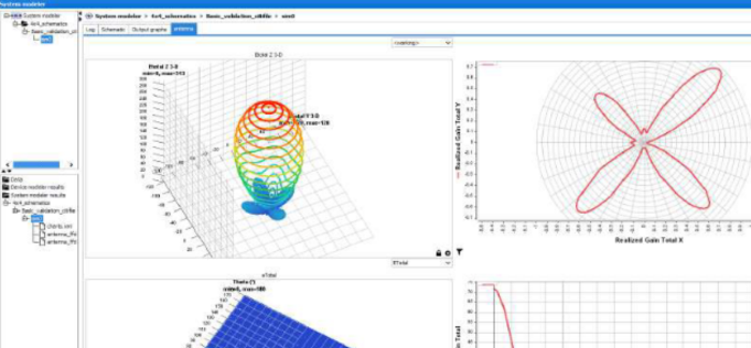
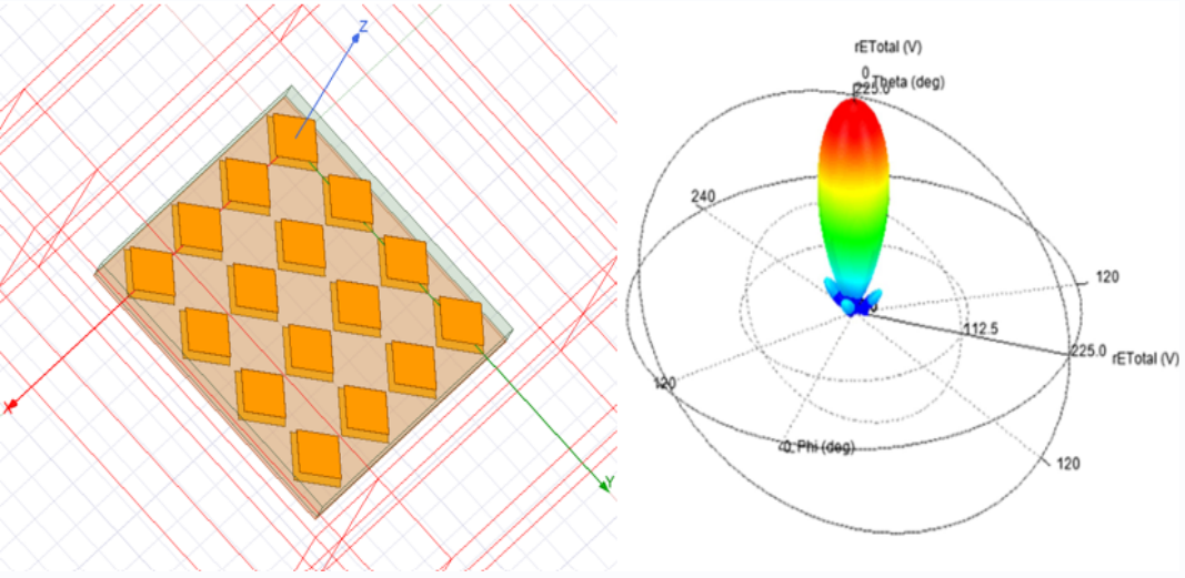
The radiation pattern of the multi-port antenna array displayed in the EM simulator interface, provides then a realistic representation of the signal emitted by the antenna. The interactions between the antenna and the RF circuits are properly managed.
Couplings between antenna ports, depending on the antenna’s pointing, can create active SWR phenomena, disrupting the operation of upstream power amplifiers. If this interaction is not taken into account, system simulation may prove inaccurate in certain cases.